
Index 446
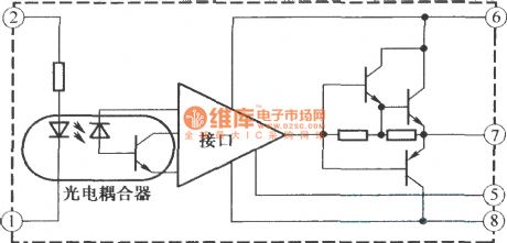
TX-KDl02 MOSFET or IGBT functional block diagram
Published:2011/4/8 0:37:00 Author:muriel | Keyword: MOSFET, IGBT, functional block diagram
View full Circuit Diagram | Comments | Reading(541)
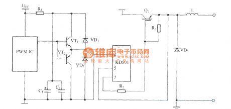
TX-KD501 application cording diagram(driver)
Published:2011/4/8 0:37:00 Author:muriel | Keyword: TX-KD501, application cording diagram, driver
View full Circuit Diagram | Comments | Reading(586)
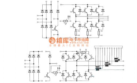
Standard MiniSkiip circuit
Published:2011/4/8 0:36:00 Author:muriel | Keyword: MiniSkiip circuit
View full Circuit Diagram | Comments | Reading(473)
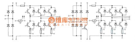
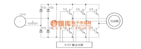
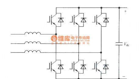
Schematic diagram of Frequency converter control drive main circuit
Published:2011/4/8 0:35:00 Author:muriel | Keyword: Frequency converter, control drive main circuit
View full Circuit Diagram | Comments | Reading(466)
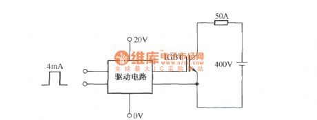
Testing EXB850 overcurrent waveform circuit
Published:2011/4/7 22:58:00 Author:muriel | Keyword: overcurrent waveform circuit
View full Circuit Diagram | Comments | Reading(483)
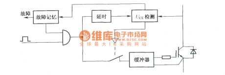
SKHI series driver detection schematic circuit diagram
Published:2011/4/7 22:58:00 Author:muriel | Keyword: driver etection
View full Circuit Diagram | Comments | Reading(441)
Application cording diagram of TX-KDl02
Published:2011/4/8 0:38:00 Author:muriel | Keyword: application cording diagram, KD10X
View full Circuit Diagram | Comments | Reading(437)
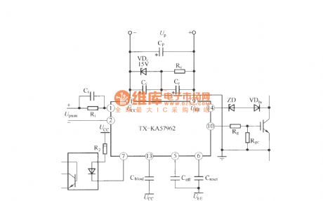
TX—KA57962 IGBT driver application cording diagram
Published:2011/4/8 0:38:00 Author:muriel | Keyword: IGBT driver, application cording diagram
View full Circuit Diagram | Comments | Reading(628)
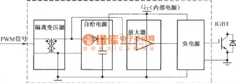
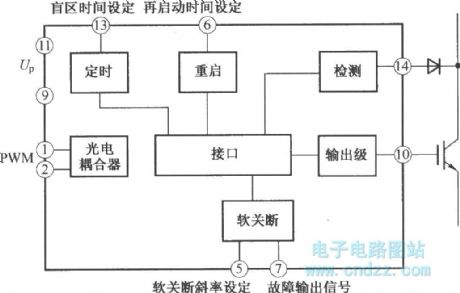
TX-KA57962 IGBT driver functional block diagram
Published:2011/4/8 0:39:00 Author:muriel | Keyword: IGBT driver, functional block diagram
View full Circuit Diagram | Comments | Reading(446)
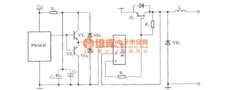
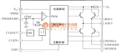
Internal structure schematic diagram of SA08 pulse width modulator
Published:2011/4/7 22:57:00 Author:muriel | Keyword: Internal structure schematic diagram , pulse width , modulator
View full Circuit Diagram | Comments | Reading(626)
M57957L/M57958L internal structure and working principle diagram
Published:2011/4/10 22:51:00 Author:may | Keyword: internal structure, working principle
M579 series driver is a kind of series driver module offer for IGBT driver produced by MITSUBISH company.
(View)
View full Circuit Diagram | Comments | Reading(531)
DC 12V sine AC 22Dv, 50N, 10W converter
Published:2011/4/14 4:18:00 Author:may | Keyword: DC 12V sine AC 22Dv, 50N, 10W, converter
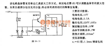
The transistor in this circuit adopts the working mode of single side class b amplification. It can adjust the amplification factor of transistor by potentiometer R3. We must consider the corresponding frequency variation if load part including idle component.
Main technical data:
Battery voltage: 12V
Battery current: 2.5A
Output voltage: 220V, 50Hz
Rated output power: 10W
Transistor loss power: 7W
Cooling plate area: 200cm2
Transformer data:
n1=65turns, 1.2mm copper lacquered wire
n2=650turns, 0.29mm copper lacquered wire
n1=2050turns, 0.14mm copper lacquered wire
n1=100turns, 0.45mm copper lacquered wire
(View)
View full Circuit Diagram | Comments | Reading(795)
MCU and RS232 serial interface wiring diagram circuit
Published:2011/3/25 3:17:00 Author:may | Keyword: MCU and RS232 serial interface wiring diagram

MCU and RS232 serial interface wiring diagram circuit is shown in the diagram:
(View)
View full Circuit Diagram | Comments | Reading(2193)
87lpc76 serial port circuit
Published:2011/3/25 3:15:00 Author:may | Keyword: serial port
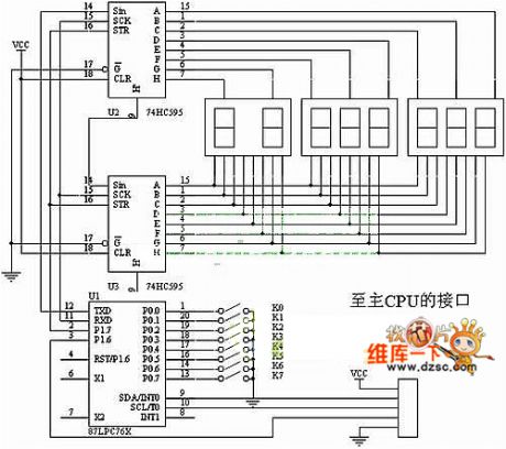
87lpc76 serial port circuit is show in the following diagram:
(View)
View full Circuit Diagram | Comments | Reading(475)
Reading and writing posture reminder
Published:2011/4/18 19:59:00 Author:Ecco | Keyword: Reading , writing , posture , reminder
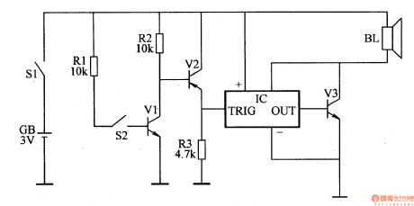
When primary and secondary students do reading and writing, it is easy to affect the visual and physical health with wrong sitting position for a long time. This example describes the reading and writing posture reminder, it can help the user correct the posture by emitting the warning sounds when the position of the user is not correct.
The working principle.
Reading and writing posture reminder circuit is composed ofelectronic switch circuit, alarm circuit and power circuit, it is shown as the Figure 9-160.
Electronic switching circuit is composedof the glass shell mercury switch S2, the transistor Vl, V2 and resistors
Alarm circuitis composed ofthe integrated circuit IC, audio amplification tube V3and speaker BL.
The power supply circuit is composed of power supply GB and power switch Sl.
Turning the power switch Sl, the powersupply GBprovides operating voltage for the machine.
(View)
View full Circuit Diagram | Comments | Reading(706)
Active input rectifier circuit
Published:2011/4/18 6:02:00 Author:May | Keyword: Active input, rectifier
View full Circuit Diagram | Comments | Reading(559)
Buick GL8 air flow meter and evaporative emission circuit
Published:2011/4/18 7:19:00 Author:Jessie | Keyword: air flow meter, evaporative emission
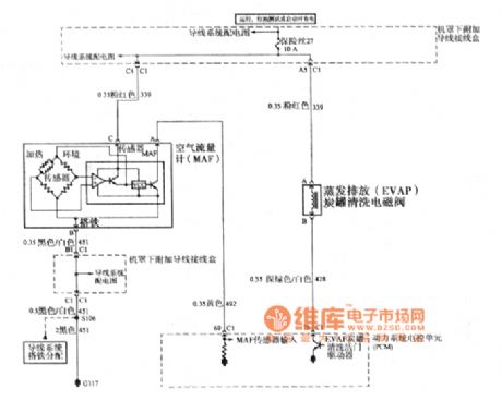
View full Circuit Diagram | Comments | Reading(611)
CMOS Logic probe circuit
Published:2011/3/22 1:54:00 Author:muriel | Keyword: CMOS, Logic probe circuit
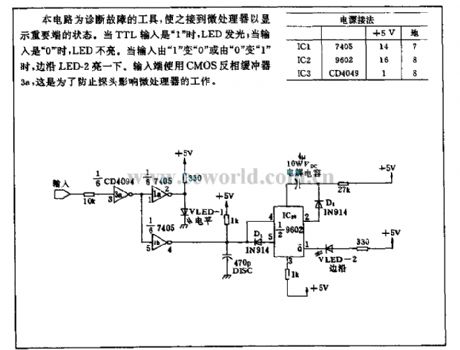
This circuit is a tool for the diagnosis of failure to display important state after link to microprocessors. When the TTL input is 1 , LED light; when the input is 0 , LED does not light. When the input from the 1 to 0 or 0 to 1 , the edge of the LED-2 light once. Input end use CMOS inverter buffer 3a, that can prevent the probe influence microprocessor. (View)
View full Circuit Diagram | Comments | Reading(1232)
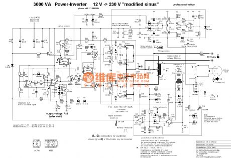
The circuit diagram of inverter with 12V-230V 1KW
Published:2011/3/22 21:03:00 Author:muriel | Keyword: inverter, 12V-230V, 1KW, TL081, CD4013, CA3130, BCY79, μA741, BS250, 2N7000
View full Circuit Diagram | Comments | Reading(3419)
The connection circuit diagram of speaker and high bass frequency divider
Published:2011/4/14 2:19:00 Author:Ecco | Keyword: speaker , high bass frequency divider

The connectionmethod of speaker and high bass frequency divider is shown as the chart 212: The inductors and the bass speakers connect in series, capacitors and the tweeter connect in series. The capacitor is used as AC capacitor that made by two small-capacity capacitors, inductance coil can be self-made. If it's a 10-inch box speaker, and the power is between 5 ~ 10W, the inductance coi could choose the size of 0.85mH. If chosen an empty skeleton with the core diameter in 3cm, it can be made by the line with the diameter in 0.8 to 1.0 mm and rolled with 300 laps.
(View)
View full Circuit Diagram | Comments | Reading(500)
| Pages:446/471 At 20441442443444445446447448449450451452453454455456457458459460Under 20 |
Circuit Categories
power supply circuit
Amplifier Circuit
Basic Circuit
LED and Light Circuit
Sensor Circuit
Signal Processing
Electrical Equipment Circuit
Control Circuit
Remote Control Circuit
A/D-D/A Converter Circuit
Audio Circuit
Measuring and Test Circuit
Communication Circuit
Computer-Related Circuit
555 Circuit
Automotive Circuit
Repairing Circuit