Circuit Diagram
Index 2136
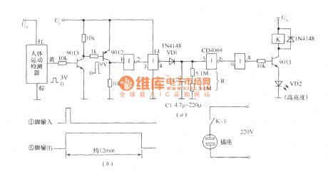
Automatic open switch lights device circuit and oscillogram
Published:2011/4/6 20:40:00 Author:Rebekka | Keyword: switch lights device , circuit and oscillogram
View full Circuit Diagram | Comments | Reading(788)
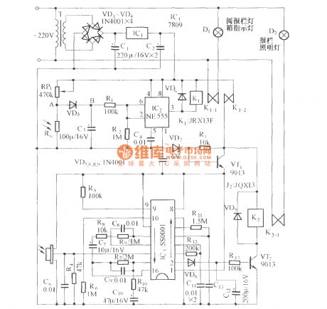
Bulletin board automatic control Lamp circuit diagram
Published:2011/4/6 20:59:00 Author:Rebekka | Keyword: automatic control Lamp , Bulletin board Lamp
View full Circuit Diagram | Comments | Reading(599)
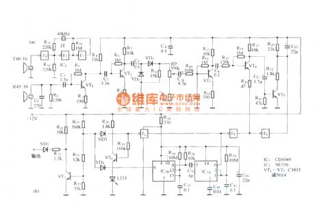
Long-range infrared remote circuit diagram
Published:2011/4/6 1:08:00 Author:Rebekka | Keyword: Long-range infrared remote

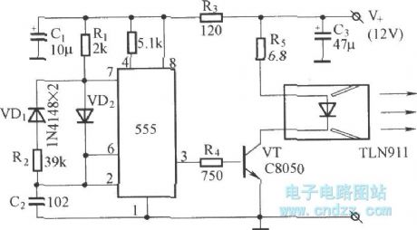
The circuit consists of infrared, infrared receiver and the implementation circuits.
IR emitter is shown as below:
(View)
View full Circuit Diagram | Comments | Reading(2348)
Infrared sensor music outlet control circuit with HT-7610A
Published:2011/4/6 1:13:00 Author:Rebekka | Keyword: Infrared sensor , music outlet control
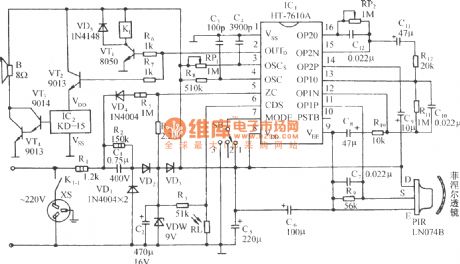
Circuit is shown as below. It includes pyroelectric infrared sensor, infrared sensor specific integrated control circuit, relay control circuit, the music for the voice circuit and 9V power supply. (View)
View full Circuit Diagram | Comments | Reading(1052)
Multi-purpose ultrasonic probe circuit diagram
Published:2011/4/6 0:59:00 Author:Rebekka | Keyword: ultrasonic probe
View full Circuit Diagram | Comments | Reading(612)
Multi-purpose eyesight protector circuit diagram
Published:2011/4/6 1:00:00 Author:Rebekka | Keyword: eyesight protector
View full Circuit Diagram | Comments | Reading(487)
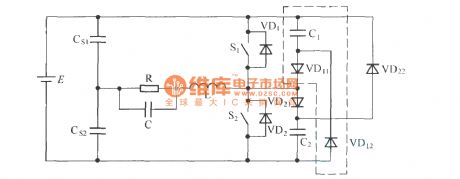
The circuit of C-2D type passive non loss buffer circuit application in DC/AC half bridge converter
Published:2011/4/10 21:43:00 Author:may | Keyword: passive, non , loss buffer, DC/AC half bridge converter
View full Circuit Diagram | Comments | Reading(463)
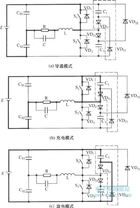
The working model of C-2D type passive non loss buffer circuit
Published:2011/4/10 21:39:00 Author:may | Keyword: working model, passive, non loss, buffer
View full Circuit Diagram | Comments | Reading(587)
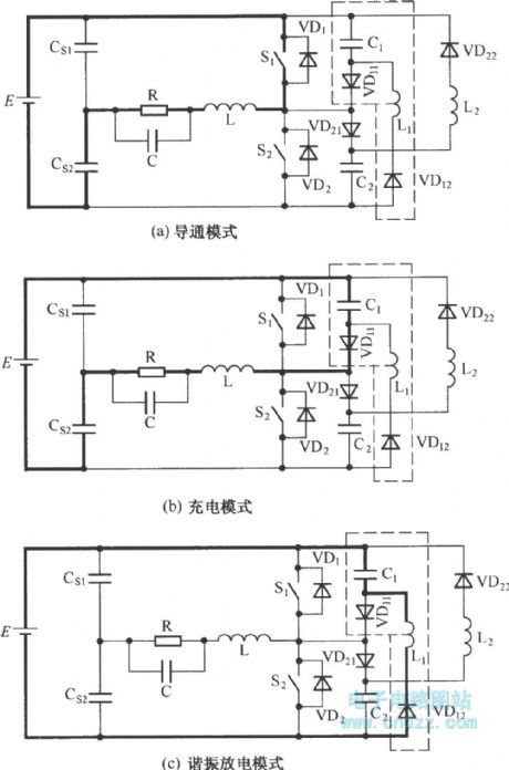
The working model of C-L-2D type passive non loss buffer circuit
Published:2011/4/10 21:38:00 Author:may | Keyword: working model, passive, non loss, buffer
View full Circuit Diagram | Comments | Reading(472)
Ultrasonic sensor electrical property circuit diagram
Published:2011/4/6 1:03:00 Author:Rebekka | Keyword: Ultrasonic sensor, electrical property
View full Circuit Diagram | Comments | Reading(694)
The application circuit of EXB841
Published:2011/4/10 21:28:00 Author:may | Keyword: application
View full Circuit Diagram | Comments | Reading(1017)
UCM type sonac technical data
Published:2011/4/6 21:02:00 Author:Rebekka | Keyword: UCM type, sonac technical data
View full Circuit Diagram | Comments | Reading(572)
The principle circuit of EXB841
Published:2011/4/10 21:30:00 Author:may
View full Circuit Diagram | Comments | Reading(1821)
The application circuit of EXB850
Published:2011/4/10 21:31:00 Author:may
View full Circuit Diagram | Comments | Reading(740)
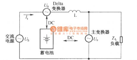
Delta alternate type UPS equivalent circuit
Published:2011/4/10 21:33:00 Author:may | Keyword: Delta alternate type
View full Circuit Diagram | Comments | Reading(509)
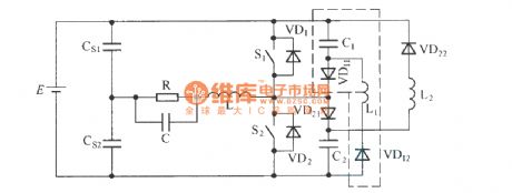
C-L-2D type passive non loss buffer circuit
Published:2011/4/10 21:37:00 Author:may | Keyword: passive, non loss, buffer
View full Circuit Diagram | Comments | Reading(467)
The basic principle of static switch
Published:2011/4/7 22:10:00 Author:may | Keyword: static switch

The usage of static switch: it can parallel normal work only when two AC power supply has the same frequency, amplitude. When one AC power supply go wrong, will generate restoring current between the two power supply, thereby make changes of output voltage in two parallel power supply, it will influence the reliable of power supply. The usage of static switch is cut the error power supply to output, and accomplish unbroken switchover between inverter output and commercial power bypass output. We mostly adopts high-speed relay as switching device, because its switching time only has 2ms~5ms, is fit for the requirement of communication equipment needing power supply without interruption. In the case of UPS power supply with capacity above 2KVA, because the increase of relay working current, its switching time will add to 80ms~120ms, and sparkle generated in the moment relay snapping will cause high temperature to damage the contact point, or voltaic arc generated between normal open and normal close contact point will short circuit the two AC power supply in a moment, so relay using for switching is only limit to low capacity UPS power supply, but its switching time has tens seconds. (View)
View full Circuit Diagram | Comments | Reading(3104)
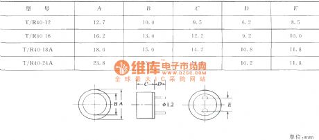
The shape and size of T/R40 type sonac
Published:2011/4/6 21:04:00 Author:Rebekka | Keyword: T/R40 type sonac, shape and size
View full Circuit Diagram | Comments | Reading(508)
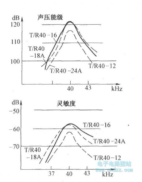
Ultrasonic sensor frequency features circuit diagram
Published:2011/4/6 1:04:00 Author:Rebekka | Keyword: Ultrasonic sensor , frequency features
View full Circuit Diagram | Comments | Reading(593)
Human body induction alarm circuit diagram
Published:2011/4/6 21:56:00 Author:Rebekka | Keyword: Human body induction, Alarm circuit
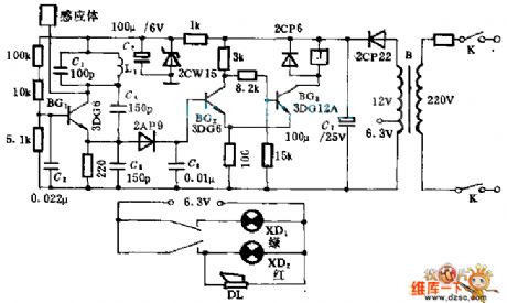
The alarm circuit is a alarm device that makes use of the distributed capacitance of the human body and to work. The multivibrator type oscillator composed of BG1, L1, C1 works but the relay does not before a human body access the alarm; When a human body access the alarm, the periodic circuit will stop work and the alarm will work because of the capacitance of human body. (View)
View full Circuit Diagram | Comments | Reading(1196)
| Pages:2136/2234 At 2021212122212321242125212621272128212921302131213221332134213521362137213821392140Under 20 |
Circuit Categories
power supply circuit
Amplifier Circuit
Basic Circuit
LED and Light Circuit
Sensor Circuit
Signal Processing
Electrical Equipment Circuit
Control Circuit
Remote Control Circuit
A/D-D/A Converter Circuit
Audio Circuit
Measuring and Test Circuit
Communication Circuit
Computer-Related Circuit
555 Circuit
Automotive Circuit
Repairing Circuit
