Circuit Diagram
Index 2132
Santana AFE type engine M.1.5.4 type electronic control system circuit diagram
Published:2011/4/11 0:40:00 Author:muriel | Keyword: Santana , AFE type engine, M.1.5.4 type electronic control system
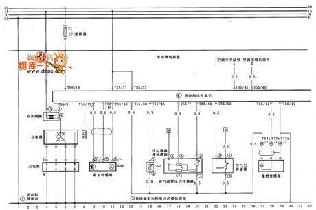
Santana AFE type engine M.1.5.4 type electronic control system circuit diagram as shown
(View)
View full Circuit Diagram | Comments | Reading(599)
Composed of LM2641 5V/3A, 3.3V/4A, 12V/0.3A and 5V/0.025A four outputs power supply circui diagram
Published:2011/4/1 3:18:00 Author:Rebekka | Keyword: four output , power supply

Composed of LM2641 5V/3A, 3.3V/4A, 12V/0.3A and 5V/0.025A four outputs power supply circui diagram. LM2641 is a dual adjustable step-down switch power supply controller. Output voltage 5.5~30V, 2.2~8V, dual output adjustable, working rate 300kHz, load regulation error 0.5%. Soft start available, with undervoltage and overvoltage protection.
(View)
View full Circuit Diagram | Comments | Reading(1216)
Santana AFE type engine M.1.5.4 type electronic control system circuit diagram (one)
Published:2011/4/11 0:39:00 Author:muriel | Keyword: Santana , AFE type engine, M.1.5.4 type electronic control system
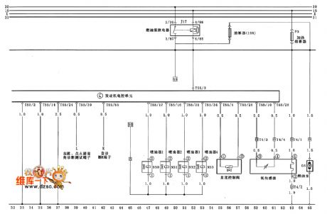
Santana AFE type engine M.1.5.4 type electronic control system circuit diagram (one) as shown
(View)
View full Circuit Diagram | Comments | Reading(699)
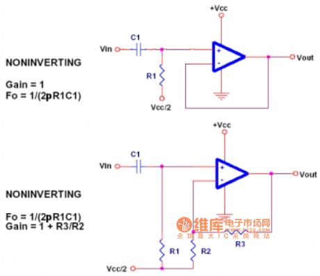
Operation amplifier high-pass filter circuit diagram
Published:2011/4/11 2:16:00 Author:Jessie | Keyword: Operation amplifier, high-pass filter
View full Circuit Diagram | Comments | Reading(869)
±5--±20V Driven tracking regulator power supply circuit diagram
Published:2011/4/1 3:18:00 Author:Rebekka | Keyword: Driven tracking regulator, power supply

±5--±20V Driven tracking regulator power supply(Driven from the negative side to positive side)circuit diagram is shown as below.
(View)
View full Circuit Diagram | Comments | Reading(558)
LM2622 adopted triple output switch power supply circuit diagram
Published:2011/4/1 3:16:00 Author:Rebekka | Keyword: triple output switch

The power circuit diagram of triple output switch posed by the LM2622 is shown as below. LM2622 is a 600kHz step-up PWM DC / DC Converter. It converts 3.3V input voltage to8V, -8V and 23V three output voltages. The output current can up to l.6A. You can use filters and low noise components, the voltage can be as low as 2.0V.
(View)
View full Circuit Diagram | Comments | Reading(1734)
Composed of MAX1822 and MAX333 1~4 channel load switch circuit diagram
Published:2011/4/1 3:14:00 Author:Rebekka | Keyword: 1~4 channel load switch

Composed of MAX1822 and MAX333 1~4 channel load switch circuit diagram is shown as below. MAX333 is composed of four amplifiers. When the switch signal SWl ~ SW4 provided to the MAX333 and MAX1822 input signal with the same N01 ~ N04, Comparison of the corresponding output of the amplifier COMl ~ COM4 is high, so the load connected to the corresponding switch.
(View)
View full Circuit Diagram | Comments | Reading(1702)
Composed of MAX1822 and 74C906 1~6 channel load switches circuit diagram
Published:2011/4/1 3:12:00 Author:Rebekka | Keyword: 1~6 channel load switches

Composed of MAX1822 and 74C906 1~6 channel load switches circuit diagram is shown as below.
MAX1822 is charge pump power supply, its input voltage is in the range of 3.5~16v selection, its output voltage is 11V. You can drive low-impedance N-channel MOSFET. 74C96 is six inverter, SWI~SW6 6 switch signals can be feeded at the same time, alone or in random combinations. This is determinedby requirments for the working condition of load swiches. (View)
View full Circuit Diagram | Comments | Reading(1484)
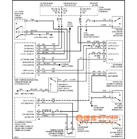
Santana full Vehicle circuit diagram
Published:2011/4/10 22:31:00 Author:muriel | Keyword: Santana, full Vehicle
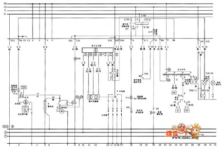
Santana full Vehicle circuit diagram as shown
(View)
View full Circuit Diagram | Comments | Reading(485)
Cadillac alarm system circuit
Published:2011/4/11 2:15:00 Author:Jessie | Keyword: alarm system
View full Circuit Diagram | Comments | Reading(633)
Santana full vehicle circuit diagram (one)
Published:2011/4/11 0:48:00 Author:muriel | Keyword: Santana, full vehicle
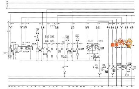
Santana full vehicle circuit diagram (one) as shown
(View)
View full Circuit Diagram | Comments | Reading(552)
Santana full vehicle circuit diagram(two)
Published:2011/4/11 0:49:00 Author:muriel | Keyword: Santana , full vehicle
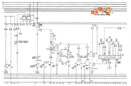
Santana full vehicle circuit diagram(two) as shown
(View)
View full Circuit Diagram | Comments | Reading(689)
Santana full vehicle circuit diagram(three)
Published:2011/4/11 0:50:00 Author:muriel | Keyword: Santana , full vehicle
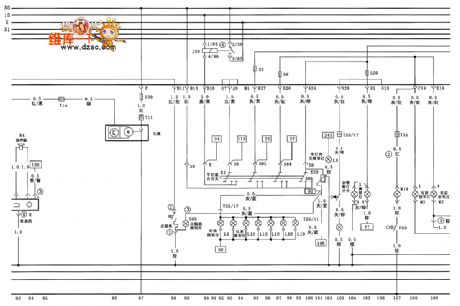
Santana full vehicle circuit diagram(three) as shown
(View)
View full Circuit Diagram | Comments | Reading(529)
Santana full vehicle circuit diagram(nine)
Published:2011/4/10 22:41:00 Author:muriel | Keyword: Santana, full vehicle

Santana full vehicle circuit diagram(nine) as shown
(View)
View full Circuit Diagram | Comments | Reading(621)
±15V Tracking regulator power supply circuit diagram 5
Published:2011/4/1 3:12:00 Author:Rebekka | Keyword: Tracking Regulator

±15V Tracking regulator power supply circuit diagram 5 is shown as below.
(View)
View full Circuit Diagram | Comments | Reading(678)
Santana full vehicle circuit diagram(ten)
Published:2011/4/10 22:39:00 Author:muriel | Keyword: Santana , full vehicle
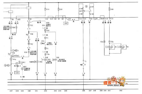
Santana full vehicle circuit diagram(ten) as shown
(View)
View full Circuit Diagram | Comments | Reading(508)
±15V Tracking regulator power supply circuit diagram 4
Published:2011/4/1 3:11:00 Author:Rebekka | Keyword: Tracking Regulator

±15V Tracking regulator power supply circuit diagram 4 is shown as below.
(View)
View full Circuit Diagram | Comments | Reading(644)
Composed of 4 codes synchronous step-down controller CS5150H 12V bias voltage 3.3V to 2.5V/7.0A converter circuit diagram
Published:2011/4/1 3:10:00 Author:Rebekka | Keyword: step-down controller , Composed of CS5150H, 3.3V to 2.5V/7.0A converter

Composed of 4 codes synchronous step-down controller CS5150H 12V bias voltage 3.3V to 2.5V/7.0A converter circuit diagram is shown as below.
4-bit DAC codes feature:
(View)
View full Circuit Diagram | Comments | Reading(638)
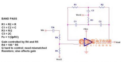
Computing single op-amp realization circuit diagram
Published:2011/4/11 2:10:00 Author:Jessie | Keyword: Computing single op-amp
View full Circuit Diagram | Comments | Reading(539)
Composed of 4 codes synchronous step-down controller CS5150H 5.0V to 3.3V/10A converter circuit diagram
Published:2011/4/1 3:07:00 Author:Rebekka | Keyword: step-down controller , 5.0V to 3.3V/10A converter

Composed of 4 codes synchronous step-down controller CS5150H 5.0V to 3.3V/10A converter circuit diagram is shown as below.
(View)
View full Circuit Diagram | Comments | Reading(709)
| Pages:2132/2234 At 2021212122212321242125212621272128212921302131213221332134213521362137213821392140Under 20 |
Circuit Categories
power supply circuit
Amplifier Circuit
Basic Circuit
LED and Light Circuit
Sensor Circuit
Signal Processing
Electrical Equipment Circuit
Control Circuit
Remote Control Circuit
A/D-D/A Converter Circuit
Audio Circuit
Measuring and Test Circuit
Communication Circuit
Computer-Related Circuit
555 Circuit
Automotive Circuit
Repairing Circuit
