
Circuit Diagram
Index 2128
Audi A6 saloon car air bag and safety belt circuit diagram one
Published:2011/4/7 2:37:00 Author:muriel | Keyword: Audi, saloon car , air bag , safety belt
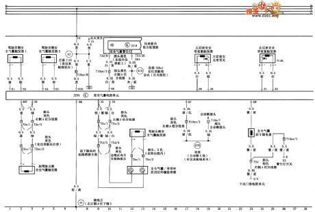
Air bag and safety belt tightener circuit diagram as shown
(View)
View full Circuit Diagram | Comments | Reading(848)
Audi A6 saloon car air-conditioner circuit diagram four
Published:2011/4/7 2:35:00 Author:muriel | Keyword: Audi, saloon car , air-conditioner

Instrument board air outlet floodlight、air fan electronic control unit and air-condition pressure switch circuit diagram as shown:
(View)
View full Circuit Diagram | Comments | Reading(2336)
Audi A6 saloon car seat circuit diagram one
Published:2011/4/7 2:34:00 Author:muriel | Keyword: Audi, saloon car seat
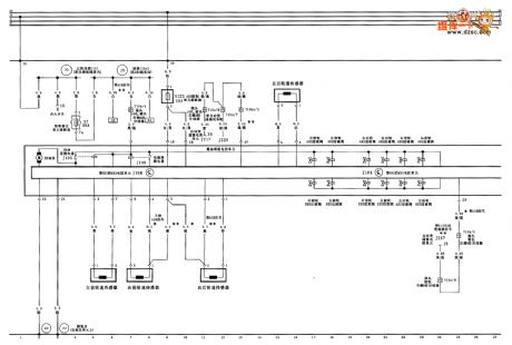
Anti-lock braking system (ABS) 、wheel speed sensor circuit diagram as shown:
(View)
View full Circuit Diagram | Comments | Reading(1952)
Audi A6 saloon car seat、rearview mirror circuit diagram two
Published:2011/4/7 2:33:00 Author:muriel | Keyword: Audi, saloon car seat, rearview mirror
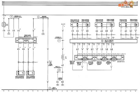
Pilot set waist adjustment、Pilot set waist longitudinal and height control circuit diagram as shown:
(View)
View full Circuit Diagram | Comments | Reading(745)
Audi A6 saloon car seat、rearview mirror circuit diagram three
Published:2011/4/7 2:33:00 Author:muriel | Keyword: Audi, saloon car seat, rearview mirror
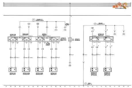
Second pilot seat regulate and second pilot seat longitudinal regulate circuit diagram as shown:
(View)
View full Circuit Diagram | Comments | Reading(591)
Four-phase stepper motor step signal circuit
Published:2011/3/22 3:24:00 Author:may | Keyword: stepper motor

diagram: Four-phase stepper motor step signal circuit
This stepper motor is four-phase stepper motor, use unipolarity DC source supply. Only breakover to stepper motor through each phase by a suitable timing, can rotate it. Diagram 1 is this four-phase stepper motor reaction working principle sketch. (View)
View full Circuit Diagram | Comments | Reading(3133)
Body light、trunk floodlight、license plate lamp and radio circuit diagram
Published:2011/4/10 20:31:00 Author:muriel | Keyword: Body light, trunk floodlight, license plate lamp , radio
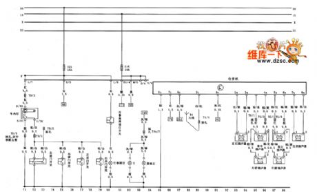
Body light、trunk floodlight、license plate lamp and radio circuit diagram (View)
View full Circuit Diagram | Comments | Reading(550)
PWM motor speed control circuit
Published:2011/3/22 3:16:00 Author:may | Keyword: PWM motor speed control

diagram: PWM motor speed control circuit (View)
View full Circuit Diagram | Comments | Reading(1298)
3-phase reaction stepping motor driver circuit diagram
Published:2011/3/24 22:30:00 Author:may | Keyword: 3-phase reaction stepping motor driver

diagram: 3-phase reaction stepping motor driver circuit diagram (View)
View full Circuit Diagram | Comments | Reading(2992)
Braking、electronic differential lock and TCS electronic control unit circuit diagram
Published:2011/4/10 20:30:00 Author:muriel | Keyword: Braking, electronic differential lock , TCS electronic control unit, FAM boar, 1.8L, saloon car
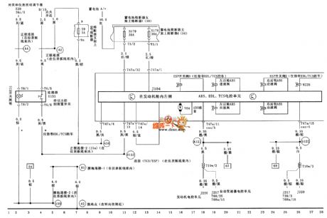
FAW bora (1.8L) saloon car braking、electronic differential lock and TCS electronic control unit circuit diagram as shown
(View)
View full Circuit Diagram | Comments | Reading(1784)
Braking、electronic differential lock and TCS electronic control unit circuit diagram(add one)
Published:2011/4/10 20:29:00 Author:muriel | Keyword: Braking, electronic differential lock , TCS electronic control unit, FAM boar, 1.8L, saloon car
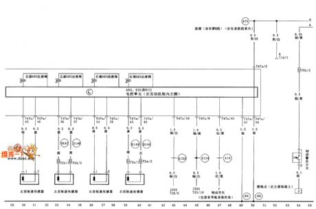
FAW bora (1.8L) saloon car braking、electronic differential lock and TCS electronic control unit circuit diagram(add one) as shown
(View)
View full Circuit Diagram | Comments | Reading(999)
Braking、electronic differential lock and TCS electronic control unit circuit diagram(add two)
Published:2011/4/10 20:29:00 Author:muriel | Keyword: Braking, electronic differential lock , TCS electronic control unit, FAM boar, 1.8L, saloon car
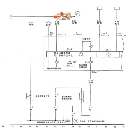
FAW bora (1.8L) saloon car braking、electronic differential lock and TCS electronic control unit circuit diagram(add two) as shown
(View)
View full Circuit Diagram | Comments | Reading(1336)
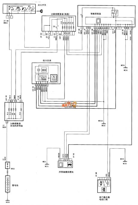
Dongfeng Citroen Picasso(2.0L) saloon car warning circuit diagram for not turning off the car light
Published:2011/4/10 20:28:00 Author:muriel | Keyword: Dongfeng Citroen Picasso, 2.0L, saloon car , warning circuit , not turning off the car light
Dongfeng Citroen Picasso(2.0L) saloon car warning circuit diagram for not turning off the car light as shown
(View)
View full Circuit Diagram | Comments | Reading(603)
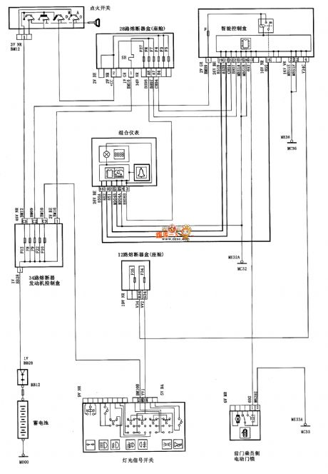
Dongfeng Citroen Picasso(2.0L) saloon car warning circuit diagram for not taking down the key
Published:2011/4/10 20:27:00 Author:muriel | Keyword: Dongfeng Citroen Picasso, 2.0L, saloon car, warning circuit, not taking down the key
Dongfeng Citroen Picasso(2.0L) saloon car warning circuit diagram for not taking down the key as shown
(View)
View full Circuit Diagram | Comments | Reading(620)
Rear air window heating raise block device and windshield wiper circuit diagram
Published:2011/4/11 2:12:00 Author:muriel | Keyword: Rear air window heating raise block device, windshield wiper
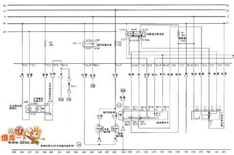
Figure Rear air window heating raise block device and windshield wiper circuit diagram (View)
View full Circuit Diagram | Comments | Reading(696)
Audi A6 saloon car 1.86 engine(ANQ) circuit diagram five
Published:2011/4/10 20:51:00 Author:muriel | Keyword: Audi , saloon car , 1.86 engine(ANQ)
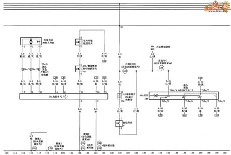
Speed electronic control unit、car external ambient temperature switch、brake switch and vacuum pump circuit diagram as shown (View)
View full Circuit Diagram | Comments | Reading(514)
Buick ABS brake lamp switch input and torque control circuit diagram
Published:2011/4/7 2:43:00 Author:muriel | Keyword: Buick , ABS brake lamp switch output, torque control
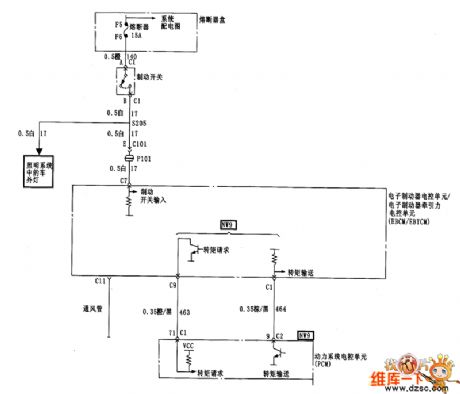
Figure Buick ABS brake lamp switchinput and torque control circuit diagram (View)
View full Circuit Diagram | Comments | Reading(959)
Audi A6 saloon car 2.4L/2.8L engine control system circuit diagram three
Published:2011/4/7 2:50:00 Author:muriel | Keyword: Audi, saloon car , 2.4L, 2.8L , engine control system

Fuel pump relay、oxygen sensor and air flowmeter circuit diagram as shown
(View)
View full Circuit Diagram | Comments | Reading(839)
Tianjin VIOS vehicle security system circuit diagram
Published:2011/4/7 2:30:00 Author:muriel | Keyword: Tianjin VIOS, vehicle , security system

Tianjin VIOS vehicle security system circuit diagram, as shown:
(View)
View full Circuit Diagram | Comments | Reading(1898)
Programmable frequency divider time delay circuit diagram with 74LS292
Published:2011/4/5 20:33:00 Author:muriel | Keyword: Programmable , frequency divider , time delay
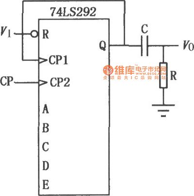
Programmable frequency divider time delay circuit with 74LS292
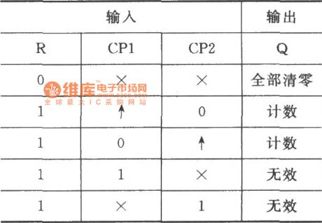
74LS292 function table
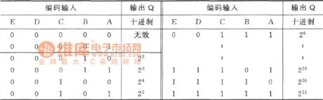
frequency division programmable table
(View)
View full Circuit Diagram | Comments | Reading(1487)
| Pages:2128/2234 At 2021212122212321242125212621272128212921302131213221332134213521362137213821392140Under 20 |
Circuit Categories
power supply circuit
Amplifier Circuit
Basic Circuit
LED and Light Circuit
Sensor Circuit
Signal Processing
Electrical Equipment Circuit
Control Circuit
Remote Control Circuit
A/D-D/A Converter Circuit
Audio Circuit
Measuring and Test Circuit
Communication Circuit
Computer-Related Circuit
555 Circuit
Automotive Circuit
Repairing Circuit