
Circuit Diagram
Index 2138
Led lamps controller 2
Published:2011/4/7 2:23:00 Author:Ecco | Keyword: Led lamps controller

View full Circuit Diagram | Comments | Reading(601)
Motor control circuit diagram braked by three-phase half-wave rectifier
Published:2011/4/10 20:42:00 Author:Ecco | Keyword: Motor control , brakinged , three-phase, half-wave, rectifier

It's motor control circuit braked by three-phase half-wave rectifier, when the AC contactor IC disconnects with the power, 2C, SJ time relays take action immediately, 2X main contact short connects with three winding lead wires of motor and then connects with Three-phase half wave rectifying power supply, then stator windingof motor is connected to parallel symmetrical line of which one end connects to null line. That is to achieve the purpose of braking, and then SJ delayed discinnects, 2C loses electric and releases, the braking ends. The braking lines is suitable for motor star connection, it has the advantages of small volume, low cost and simple lines, but also for larger capacity motor. It's shown as the chart: (View)
View full Circuit Diagram | Comments | Reading(1319)
Led lamps controller 1
Published:2011/4/7 2:22:00 Author:Ecco | Keyword: Led lamps controller

The LED festival character display lights controller can display four sentences and four words composing of many LEDs(such as celebrating May Day and long live our motherland ), and they display in time sequence to add festive atmosphere to festive night.
Working principle:
The LED festival lights controller circuit is composed of power supply circuit, pulse generator, control circuit and LED display circuit. It's shown as the chart of 1-165.
Power supply circuit consists of step-down capacitor Cl, discharge resistors Rl, rectifier diodes VDl, VD2, Zener diode VS and filter capacitor C2.
The pulse generator is composed of integrated circuit ICl, resistors R2, R3 and capacitors C3, C4.
Control circuit consists of decimal counting / pulse divider integrated circuit IC2, diodes VD3, resistors R4-R8, capacitor C5 and thyristor VTl-VW.
(View)
View full Circuit Diagram | Comments | Reading(1497)
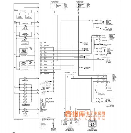
engine oil pressure switch、water temperature sensor、braking smoke and air condition system circuit diagram
Published:2011/4/10 20:39:00 Author:muriel | Keyword: engine oil pressure switch, water temperature sensor, braking smoke , air condition system
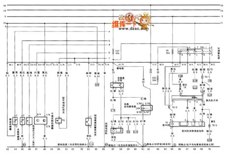
Figure engine oil pressure switch、water temperature sensor、braking smoke and air condition system circuit diagram (View)
View full Circuit Diagram | Comments | Reading(1819)
Automatic water level control circuit diagram of draining tank
Published:2011/4/7 21:20:00 Author:Ecco | Keyword: Automatic , water level control, draining tank

View full Circuit Diagram | Comments | Reading(1482)
Automatically detecting the battery voltage indicator circuit diagram
Published:2011/4/7 21:11:00 Author:Ecco | Keyword: Automatically detecting, battery voltage indicator

the battery voltage indicator
This simple circuit can detect the battery voltage. When the voltage is lower than the preset voltage set by the variable resistor VR1, LED will light up, in fact, related resistance and VR1 will be bias maintain Q2 (OFF) of Q1(ON), so that the LED is OFF. When the battery voltage is gradually reduced to below the preset voltage, Q1 becomes OFF, Q2 becomes ON, the LED lights up. This circuit can work under the 12V battery. You can first use a variable power supply, adjust the the low-voltage you want, connect to the circuit, adjust VR1 to critical value of beginning to light or dark.
(View)
View full Circuit Diagram | Comments | Reading(1676)
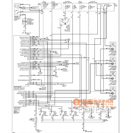
Air-condition front and back control assembly and ambient temperature control circuit diagram
Published:2011/4/10 20:25:00 Author:muriel | Keyword: Air-condition front and back control assembly, ambient temperature control
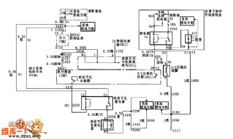
Figure Air-condition front and back control assembly and ambient temperature control circuit diagram (View)
View full Circuit Diagram | Comments | Reading(577)
The school bell timing circuit diagram
Published:2011/4/10 20:20:00 Author:Ecco | Keyword: school bell timing

General school bell is pulled by the people, but it is difficult to control the tone time. It can solve this problem by installing a timer to control ring. Working principle is shown in Figure 213: To press the button QA when pulling the bell, the time relay SJ pulls, bell ring tone is also energized, to release the button QA, as the SJ pulls, SJ normally open point is self-hold until time relay seting time(time relay could adjust to 1 minute or according to the choice), the delay normally closed point is cut off and make time relay loses electric and releases, SJ normally open point is cut off, the tone will stop.
(View)
View full Circuit Diagram | Comments | Reading(976)
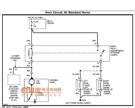
Buick horn circuit (standard configuration)
Published:2011/4/8 2:47:00 Author:Jessie | Keyword: horn
View full Circuit Diagram | Comments | Reading(504)
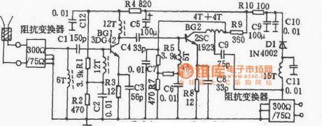
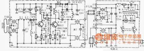
TF903 Super remote antenna amplifier circuit
Published:2011/4/8 4:42:00 Author:Jessie | Keyword: antenna amplifier
View full Circuit Diagram | Comments | Reading(455)
Buick dashboards circuit (instrument, ub3)
Published:2011/4/8 4:43:00 Author:Jessie | Keyword: dashboard
View full Circuit Diagram | Comments | Reading(433)
Aishi S903 antennas amplifier circuit
Published:2011/4/8 4:44:00 Author:Jessie | Keyword: antennas amplifier
View full Circuit Diagram | Comments | Reading(455)
Nickel-cadmium battery low voltage indication circuit diagram of remote control helicopter
Published:2011/4/7 20:43:00 Author:Ecco | Keyword: Nickel-cadmium battery , low voltage indication , remote control helicopter
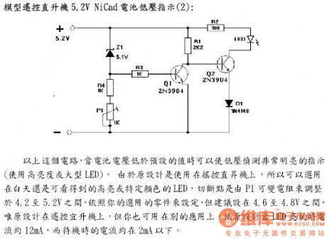
5.2V Nickel-cadmium battery low voltage indication 2 of remote control helicopter
In the circuit, when the battery voltage is lower than the preset value, the bright indication can be used as detecting low voltage (use high brightness and large LED), since the original design is used in remote control helicopter, so you can choose a a specific color LED which could be watched in the day, the cutting off point is adjusted by the variable resistor P1 of which resistance is between 4.2 to 5.2V, the selection of parts is according to your choice, but proposed to be located between 4.6 to 4.8V. The design can also be used in other applications. According to the original design, when the LED is lit, the current is about 12mA, while the standby current is about 2mA. (View)
View full Circuit Diagram | Comments | Reading(1520)
Buick remote control lock circuit diagram
Published:2011/4/8 2:51:00 Author:Jessie | Keyword: remote control lock
View full Circuit Diagram | Comments | Reading(545)
Hartley oscillating diagram
Published:2011/4/7 22:22:00 Author:Jessie | Keyword: Hartley oscillating

View full Circuit Diagram | Comments | Reading(520)
Series resonance circuit diagram
Published:2011/4/7 22:16:00 Author:Jessie | Keyword: Series resonance

View full Circuit Diagram | Comments | Reading(759)
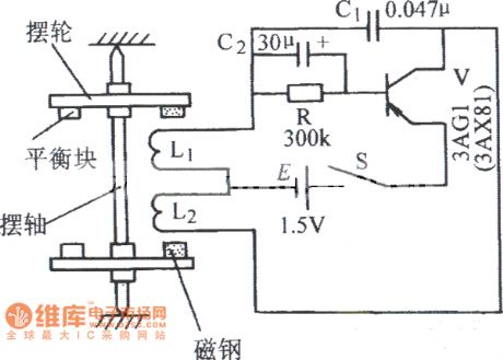
Magnetic pendulum oscillation circuit diagram
Published:2011/4/7 22:15:00 Author:Jessie | Keyword: Magnetic pendulum, oscillation
View full Circuit Diagram | Comments | Reading(3274)
Single pipe transformer oscillating circuit diagram
Published:2011/4/7 22:07:00 Author:Jessie | Keyword: Single pipe, transformer, oscillating

View full Circuit Diagram | Comments | Reading(541)
Field effect transistor low-voltage oscillating circuit diagram
Published:2011/4/8 2:45:00 Author:Jessie | Keyword: Field effect transistor, low-voltage oscillating
View full Circuit Diagram | Comments | Reading(504)
The battery voltage protection indicating circuit diagram
Published:2011/4/7 22:14:00 Author:Ecco | Keyword: battery voltage, protection indicating

Power, low battery indication
In the following circuit when the battery is OK, it indicates the green LED, the LED is the power indicator during operation. When the battery voltage is lower than the default, the red LED light will light up.
(View)
View full Circuit Diagram | Comments | Reading(970)
| Pages:2138/2234 At 2021212122212321242125212621272128212921302131213221332134213521362137213821392140Under 20 |
Circuit Categories
power supply circuit
Amplifier Circuit
Basic Circuit
LED and Light Circuit
Sensor Circuit
Signal Processing
Electrical Equipment Circuit
Control Circuit
Remote Control Circuit
A/D-D/A Converter Circuit
Audio Circuit
Measuring and Test Circuit
Communication Circuit
Computer-Related Circuit
555 Circuit
Automotive Circuit
Repairing Circuit