
Circuit Diagram
Index 1983
Chang antelope car air bag system circuit diagram
Published:2011/4/28 20:09:00 Author:Rebekka | Keyword: Chang antelope car , air bag system

1. Airbag electronic control unit (SDM) 2. Front passenger side airbag component 3. Driver's side airbag components 4. The coil connecting 6. To the diagnostic connector 7. To the ECM, etc. 8. Combination of instruments 9. Fuse 10. airbag fuse 11. Airbag control connector 12. Ignition switch 13. Connected battery positive 14. Ground 15. shorted Article
(View)
View full Circuit Diagram | Comments | Reading(1685)
TDA two chips switching power supply circuit diagram
Published:2011/4/28 9:31:00 Author:Rebekka | Keyword: two chips , switching power supply

TDA two chips switching power supply circuit diagram is shown as above. (View)
View full Circuit Diagram | Comments | Reading(3837)
Automotive electronic equipment cooling fluid temperature gauge, oil pressure gauge circuit
Published:2011/4/28 19:12:00 Author:Christina | Keyword: Automotive electronic equipment, cooling fluid temperature gauge, oil pressure gauge
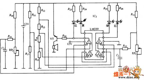
In order to understand and control the car engine's working-situation, and to detect and eliminate the failure, cars are equipped with the automotive electronic equipment cooling fluid temperature gauge, oil pressure gauge. As the figure 6-38 shown, the circuit can displays engine coolant temperature and oil pressure. It is composed of the coolant temperature sensor w1 (Thermistor type), the oil pressure sensor w2 (bimetallic resistance-type), the lm339 and the red, yellow, green light-emitting diode monitor. The coolant temperature sensor is in the engine water-jacket, the coolant temperature measurement circuit is composed of the coolant temperature sensor and resistance r11. The oil pressure sensor is in the engine's main oil pipeline, and the oil pressure measuring circuit is composed of the oil pressure sensor and resistance r18. The automotive electronic equipment cooling fluid temperature gauge, oil pressure gauge circuit is as shown:
(View)
View full Circuit Diagram | Comments | Reading(1293)
Motor PWM speed control circuit
Published:2011/4/28 18:59:00 Author:Christina | Keyword: motor, PWM, speed control

View full Circuit Diagram | Comments | Reading(488)
Fishing pulse circuit
Published:2011/4/28 18:57:00 Author:Christina | Keyword: Fishing, pulse
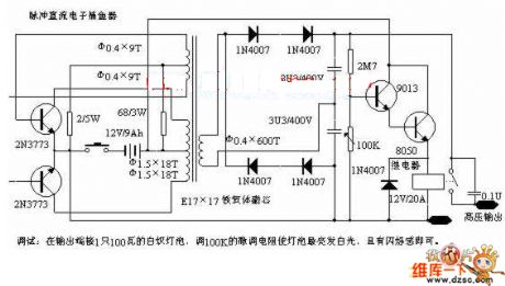
Debugging: Connect a 100W incandescent bulb to the output port of the circuit, then adjust the 100KK fine-tuning resistance to let the bulb sends out white light with light flash. (View)
View full Circuit Diagram | Comments | Reading(747)
50Ω impedance linear amplifier circuit composed of the RF2320
Published:2011/4/28 19:14:00 Author:Christina | Keyword: 50Ω, impedance linear amplifier

The 50Ω impedance linear amplifier circuit composed of the RF2320 is as shown:
(View)
View full Circuit Diagram | Comments | Reading(420)
4GHZ oscillator circuit
Published:2011/4/28 19:15:00 Author:Christina | Keyword: 4GHZ, oscillator

The 4GHZ oscillator circuit is as shown:
(View)
View full Circuit Diagram | Comments | Reading(653)
Fan automatic switch circuit
Published:2011/4/28 20:09:00 Author:Christina | Keyword: Fan, automatic switch


1.Principle circuit
The fan automatic switch circuit is as shown in figure 1. The voltage divider is composed of the PTC thermistor RT and RP, you can set the fan's temperature by regulating the RP.
Figure 1 The fan automatic switch circuit
2.Main components
The fan automatic switch circuit uses the PTC thermistor as the RT temperature sensing element, the standard resistance - temperature curve of this device is as shown in figure 2.
Figure 2. the standard resistance - temperature curve
This circuit can be used in wide range of applications such as the warehouse.
(View)
View full Circuit Diagram | Comments | Reading(713)
lm1875 application experiment and current feedback btl circuit-design circuit
Published:2011/4/28 18:49:00 Author:Christina | Keyword: application experiment, current feedback btl, circuit-design

If the current becomes DC current and changes into the current feedback, the frequency response will become broad, and the bass power significantly enhanced, the ability of frequency resolution and alto texture will increase. If we compare this amplifier with the New Texas 6800 pure class A amplifier, use the Huiwei swan m1.2 speaker, in a 15 square meters room, this amplifier is very close to New Texas 6800 pure class A amplifier.
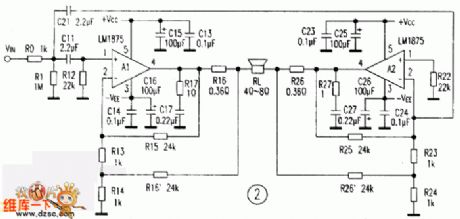
DC current negative feedback btl circuit is as shown in figure 2, abolishes the standard btl circuit's c12, c22, resistors r16 and r26 is the sample resistance, current feedback signal gets into the amplifier a1, a2 of the inverting input port through the r15、r16、r25、r26, and the resistances of r13、r14、r15、r16 determine the value of the amplifier gain.
Experiment with the circuit in Figure 2, anyway you turn off the power and input signal, DC output port has no DC current, and has no static output noise, the speaker just sends out the sound of pa when you opening it. So this experiment shows that this circuit is very stable, if you plug the input terminal when increasing the volume orin the static state, this circuit will not beself-excited. (View)
View full Circuit Diagram | Comments | Reading(3488)
Phase sequence detection circuit
Published:2011/4/28 18:50:00 Author:Christina | Keyword: Phase sequence, detection

If the motor of the drive pump, compressor or transmission belt reverse run, the equipment will be damaged. This circuit can find out whether the motor phase sequence is error, and protect the motor damaged by the rapid-heating. When the phase sequence is correct, the LED lights. When the phase sequence is not correct, the output power goes low, the LED not lights. The diode and zener convert the sine wave into rectangular logic level pulse. when the phase sequence is correct, G4 outputs a string of rectangular pulse, the pulse width is about 2.5 ns. When the phase sequence is not correct, the output power is zero. The output pulse edge's zero-crossing and B phase's zero-crossing are synchronous, so the output pulse can be used to trig the SCR and drive relay coil which are connected with the Phase B's two ends. This kind of SCR can supply power to relay only when the phase sequence is correct.
(View)
View full Circuit Diagram | Comments | Reading(8762)
Car coolant alarm circuit
Published:2011/4/28 18:52:00 Author:Christina | Keyword: Car coolant, alarm circuit

The car coolant alarm circuit is as shown in the figure. If the coolant level is normal, the sensor is grounded through the liquid, in the figure, a point has no voltage level. When switch turns on, level alarm system will check itself. Specific work process is as follows:
(1)Turn on the ignition switch, the main relay starts working. c1 is charged by the high charge current and this current maintains the t1 turns on, t2 turns on, t3 turns on, then the indicator turns on.
(2)When the c1 is full, current is gradually reduced, t1 turns off, t2 turns off, t3 turns off, then the indicator turns off.
The light-time is related with the parameters c1. When this device is checking itself, if the warning light does not shine, it means there is something wrong with the alarm system, you should check it.
(3)If the liquid level is too low, the sensor can not reach the liquid, Point a's voltage level becomes higher, t1 base potential becomes higher too, t1 turns on, t2 turns on, t3 turns on, then the indicator turns on, When this device is checking itself, if the warning light does not turns off, it means the coolant liquid level is too low, you need to fill it.
(4)When the coolant level is normal, if you turn off the switch, c1's charge-circuit is: c1(+)→r1→r11→r10→c1(-). (View)
View full Circuit Diagram | Comments | Reading(1115)
Solid-sense switch circuit to protect person and equipment
Published:2011/4/28 6:10:00 Author:TaoXi | Keyword: Solid-sense switch, protect person and equipment

The Solid-sense switch circuit to protect person and equipment is as shown
Figure 1 When the temperature of chip reaches the high set-value or low set-value, the TSC620 temperature sensing switch (produced by the Tai Leda Solid Components Inc.)is sensed by the program. When it reaches the high set-value, MOSFET turns on and then the fan. When it reaches the low set-value, it will shut down. (View)
View full Circuit Diagram | Comments | Reading(410)
SRS effect processor circuit
Published:2011/4/28 0:51:00 Author:TaoXi | Keyword: SRS, effect processor

The SRS effect processor circuit's left and right channels output the L, R, n(L+R), ±f(L-R) mixed-signal. L+R means intermediate information, n means mixing ratio ( contrast adjustment); L-R means surround information, let it goes through the 300Hz ~ 10kHz filter, you can get the f(L-R), if you change the filter, you also change the sense of space . The circuit running stereo and Dolby surround software can eliminates the sense of level , and you can feel the surround sound that you never felt.
(View)
View full Circuit Diagram | Comments | Reading(4625)
music-type fridge door-close reminding circuit composed of CIC2851E
Published:2011/4/26 21:47:00 Author:TaoXi | Keyword: music-type, fridge door-close reminding

The music-type fridge door-close reminding circuit is as shown. This circuit is composed of the rectifier voltage regulator circuit, delay circuit, music IC CIC2851E and the speaker.etc. The reduce-rectify voltage circuit supplies the 3V power to the whole circuit.
When you open the refrigerator door, switch AN turn on, capacitor C3 charged by the R3 and the base potential of the BG1 increase, after 20 minutes, voltage of C3 makes the BG1 turned on, so BG2 turns off, CIC2851E starts working, the output music signal is amplified by BG3 to drive the speaker Y send out the music of christmas. If the fridge door does not close, the music will not stop. The length of delay time can be selected by master, generally between 5 to 15 seconds. This circuit takes 20 seconds.
The circuit requires the voltage between two ends of DW is about 3V, if the voltage is too high, it is easy to damage the integrated circuits. Resistor R6 is used to adjust the speed of music rhythm, the range of R6 is 20kΩ ≤ R6 ≤ 120kΩ. (View)
View full Circuit Diagram | Comments | Reading(654)
Three-step tone controller (STK3048) circuit
Published:2011/4/28 1:44:00 Author:TaoXi | Keyword: Three-step, tone controller

The three-step tone controller circuit is as shown. Core component STK3048 is the dual-channel low-noise voltage amplification thick block, it is one kind of cheap high voltage dual operational amplifier, particularly suitable for make the front- and tone circuits. This circuit is controlled by three-stage tone. By changing the proportion of each frequency in the music signal,we canimprove the system's audio features, so we get the good sound. (View)
View full Circuit Diagram | Comments | Reading(1074)
TDA9210 integrated block typical application circuit
Published:2011/4/28 0:52:00 Author:TaoXi | Keyword: integrated block, typical application


2.Pin functions and data
The TDA7429T can be used in Konka T2168K TV, and the pin functions and data of this deviec is as shown in table 41.
Table 41 The pin functions and data of TDA7429T
3. Typical application circuit
The typical application circuit of the TDA9210 is as shown in figure 41. This circuit can be used with T-step A9535/36. The TDA9210 has no character display function in this circuit, so the pin-0 (Image-blank signal input port) has grounded. If you need to display the characters, you can input the image-blank signal from the pin-11, so ifthe characters get out, characters behind the image will be dredged .
(View)
View full Circuit Diagram | Comments | Reading(859)
TDA8350Q integrated block typical application circuit
Published:2011/4/28 8:15:00 Author:TaoXi | Keyword: integrated block, typical application circuit

TDA6111AQ--Video signal process integrated circuit
The TDA6111AQ is designed as the video signal process integrated circuit which is produced by the PHILIPS company, and it can be used in large screen, super large screen digital color TV.
1.Features
The TDA6111AQ has the video signal amplify circuit, the highlights eliminate circuit and the absorber.
2.Pin functions and data
The TDA6111AQ is in the single 9-pin package, the pin functions and data of the TDA6111AQ is as shown in table 31.
Table 31 The pin functions and data of the TDA6111AQ
TDA8350Q--Field-scann output integrated circuit
The TDA8350Q is designed as one kind of field-scann output integrated circuit which is produced by the PHILIPS company, and it can be used in domestic and imported color television sets.
1.Features
The TDA8350Q has the field excitation and the output circuit, the field flyback pulse generator circuit. The maximum output current is 2.2Ap-p, the maximum output power is 15W, the typical application circuit is as shown in figure 31.
(View)
View full Circuit Diagram | Comments | Reading(819)
Wien Oscillator Regulator Circuit
Published:2011/4/28 5:35:00 Author:Sue | Keyword: Wien Oscillator Regulator Circuit

In Wien Bridge, the change of any resistance will change frequency and attenuation. As seen in the figure, the adjustment of resistance can alter the compensation amplifier's gain, so as to compensate the change of attenuation. (View)
View full Circuit Diagram | Comments | Reading(452)
TDA8351 integrated block internal box circuit
Published:2011/4/28 8:01:00 Author:TaoXi | Keyword: integrated block, internal box circuit


TDA7050--Two-channel power amplifier IC
The TDA7050 is designed as one kind of two-channel power amplifier IC that can be used in the low voltage walkman, the repeater, the multimedia audio and other audio equipments.
1.features
The TDA7050 has the two channels of audio power preamplifiers with same function, audio power amplifier and other circuits.
2.Pin functions and data
The TDA7050 is in the 8-pin dual in-line package, the pin functions and data is as shown in the table 32.
Table 32 5-pin functions and data of the TDA7050
(View)
View full Circuit Diagram | Comments | Reading(2276)
TDA9178 integrated block internal box circuit
Published:2011/4/28 6:53:00 Author:TaoXi | Keyword: integrated block, internal box

TDA7297--Two-channel power amplifier IC
The TDA7297 is one kind of audio power amplifier which is produced by the PHILIPS company, and it can be used in TV and audio equipments.
The TDA7297 is the two-channel stereo power amplifier IC that has the M Dingwang (Mute) control function, the output power is 15Wx2. The audio output mode of the TDA7297 is BTL mode. So this device can be used in wide range of supply voltage (6-8V), and has the function of short-circuit protection, overload protection.
The TDA7297 is in the 15-pin single in-line package, the pin functions and data of the Haier Hp-2969U large screen color TV is as shown in table 38.
Table 38 the pin functions and data of TDA7297
TDA9178--Single chip YUV picture improvement processing integrated circuit
The TDA9178 is one kind of video signal process integrated circuit which is produced by the PHILIPS company, it can be used in large screen and rear projection TV such as the Changhong 51PD28A.
1.Features
The TDA9178 uses the YUV input/output mode to complete the Y, U, V signal vector-processing. This circuit includes the luminance signal transient improve circuit, the color signal transient improve circuit (CTL), the line width control circuit (OWC), the video noise reduction TV (VDC), the color clarity improve circuit (CDS).etc. In the luminance signal vector process, you can expand the black level, process the quadrant and correct Y.
The TDA9178 IC has the I(2)C bus interface circuit, and the I(2)C bus interface circuit controls the whole circuit.
The TDA9178 integrated block internal box circuit is as shown in figure 38.
(View)
View full Circuit Diagram | Comments | Reading(2132)
| Pages:1983/2234 At 2019811982198319841985198619871988198919901991199219931994199519961997199819992000Under 20 |
Circuit Categories
power supply circuit
Amplifier Circuit
Basic Circuit
LED and Light Circuit
Sensor Circuit
Signal Processing
Electrical Equipment Circuit
Control Circuit
Remote Control Circuit
A/D-D/A Converter Circuit
Audio Circuit
Measuring and Test Circuit
Communication Circuit
Computer-Related Circuit
555 Circuit
Automotive Circuit
Repairing Circuit