
Circuit Diagram
Index 1995
Using TDA as positive and negative voltage single-supply circuit diagram
Published:2011/4/27 3:49:00 Author:Rebekka | Keyword: positive and negative voltage , single-supply
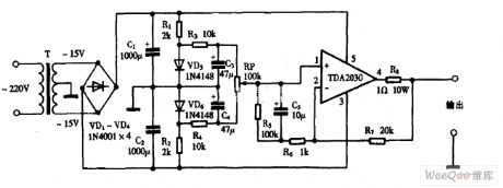
Using TDA as positive and negative voltage single-supply circuit diagram is shown as above. (View)
View full Circuit Diagram | Comments | Reading(788)
TOYOTA COASTER coach electronic control electronic speed variator circuit wiring circuit diagram
Published:2011/4/27 3:49:00 Author:Nicole | Keyword: TOYOTA COASTER, coach, electronic control, electronic speed variator

View full Circuit Diagram | Comments | Reading(886)
555 Negative voltage source circuit
Published:2011/4/27 3:47:00 Author:Ecco | Keyword: 555 , Negative, voltage source
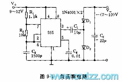
As shown in Figure 9-1, 555 and R1, R2, C3 form an astable multivibrator, f = 1.44 / (R1 +2 R2) C3, the frequency of the icon parameter is about 80kHz. R2 is greater than the R1, so the duty cycle closes to 50%. The output oscillation pulses is rectified by the D1, D2, C2, and it gets a negative voltage and offers tens of mA load current.
(View)
View full Circuit Diagram | Comments | Reading(1899)
Using TDA7052 as single-chip radio circuit diagram
Published:2011/4/27 3:46:00 Author:Rebekka | Keyword: single-chip radio circuit

Using TDA7052 as single-chip radio circuit diagram is shown as above. (View)
View full Circuit Diagram | Comments | Reading(4268)
TOYOTA COASTER coach anterior rear wiper and window washing device circuit wiring circuit diagram
Published:2011/4/27 3:45:00 Author:Nicole | Keyword: TOYOTA COASTER, coach, wiper, window washing device

View full Circuit Diagram | Comments | Reading(1642)
555 voltage detection circuit
Published:2011/4/27 3:41:00 Author:Ecco | Keyword: 555, voltage detection

As shown in Figure 7-10, the voltage detection circuit uses 555 as the core to form in bistable mode. Usually, the pin 6 of 555 (threshold level side)is connected to VDD by R1, therefore, pin 3 is in low level. The pin 2 on trigger end of 555 is connected to the measured point by a regulator DW, DW regulator is Vz, when the measured voltage is less than Vz +1/3 VDD, the 555 sets, pin 3 is high level, LED is lit. If using different value of regulators DW, it is controlled by the switch, you can distinguish the different values of the measured voltage.
(View)
View full Circuit Diagram | Comments | Reading(2110)
Using TDA2030 as DC power supply circuit diagram
Published:2011/4/27 3:44:00 Author:Rebekka | Keyword: DC power supply circuit

Using TDA2030 as DC power supply circuit diagram is shown as above. (View)
View full Circuit Diagram | Comments | Reading(5486)
Using TA7641 as wired interphone circuit diagram
Published:2011/4/27 3:43:00 Author:Rebekka | Keyword: wired interphone

Using TA7641 as wired interphone circuit diagram is shown as above. (View)
View full Circuit Diagram | Comments | Reading(1235)
Wireless transmitter module TX5 circuit diagram
Published:2011/4/27 2:13:00 Author:Rebekka | Keyword: Wireless transmitter module
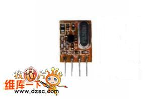
Communication: AM ASK Frequency: 315MHZ ~ 433.92MHZ Quiescent Current: ≤ 0.1UA Emission current: +10 mA Operating Voltage: DC 1.8 ~ 3.6V Operating Temperature: -24 ℃ ~ +85 ℃ Dimension: 16.5x11.2x5. 5MM Frequency Stability: ± 30KHZ Transmit power: 10dbm Launch distance: 500m (empty extension) Modulation rate: 3KB / S (View)
View full Circuit Diagram | Comments | Reading(484)
Using LM386 as multi-purpose radio circuit diagram
Published:2011/4/27 3:32:00 Author:Rebekka | Keyword: multi-purpose radio

Using LM386 as multi-purpose radio circuit diagram is shown as above. (View)
View full Circuit Diagram | Comments | Reading(3941)
TOYOTA COASTER coach automatic door(folded-type) circuit wiring circuit diagram
Published:2011/4/27 3:41:00 Author:Nicole | Keyword: TOYOTA COASTER, coach, automatic door

View full Circuit Diagram | Comments | Reading(2689)
Using LM386 as aquare-wave generator circuit diagram
Published:2011/4/27 3:33:00 Author:Rebekka | Keyword: aquare-wave generator

Using LM386 as aquare-wave generator circuit diagram is shown as above. (View)
View full Circuit Diagram | Comments | Reading(1720)
Using LM386 as audio frequency oscillator circuit diagram
Published:2011/4/27 3:35:00 Author:Rebekka | Keyword: audio frequency oscillator

Using LM386 as audio frequency oscillator circuit diagram is shown as above. (View)
View full Circuit Diagram | Comments | Reading(3914)
Using TA7641 as LED flash launcher circuit diagram
Published:2011/4/27 3:39:00 Author:Rebekka | Keyword: LED flash launcher

Using TA7641 as LED flash launcher circuit diagram is shown as above. (View)
View full Circuit Diagram | Comments | Reading(1237)
Using LM386 as speaker tester circuit diagram
Published:2011/4/27 3:36:00 Author:Rebekka | Keyword: speaker tester

Using LM386 as speaker tester circuit diagram is shown as above. (View)
View full Circuit Diagram | Comments | Reading(1962)
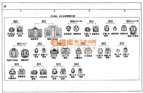
TOYOTA COASTER coach harness-to-harness connector(body cluster) circuit wiring circuit diagram
Published:2011/4/27 3:38:00 Author:Nicole | Keyword: TOYOTA COASTER, coach, connector, body cluster
View full Circuit Diagram | Comments | Reading(522)
Using SL as gas leak detector circuit diagram
Published:2011/4/27 3:37:00 Author:Rebekka | Keyword: gas leak detector

Using SL as gas leak detector circuit diagram is shown as above. (View)
View full Circuit Diagram | Comments | Reading(2978)
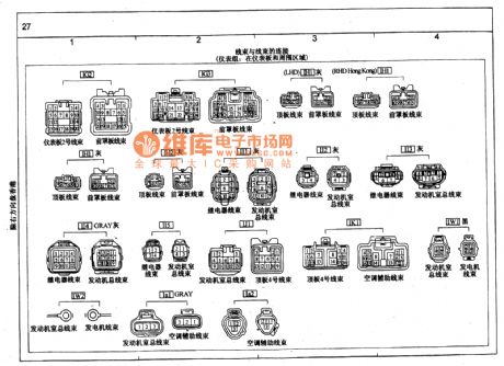
TOYOTA COASTER coach harness-to-harness connector(instrument cluster) circuit wiring circuit diagram(continuing)
Published:2011/4/27 3:36:00 Author:Nicole | Keyword: TOYOTA COASTER, coach, connector, instrument cluster
View full Circuit Diagram | Comments | Reading(616)
555 quickly resistance measuring circuit
Published:2011/4/27 3:32:00 Author:Ecco | Keyword: 555 , quickly , resistance, measuring

As shown in Figure 7-8, measuring circuit uses 555 as the core, and 555,R1, R2, R3, Rx, C1 form an astable multivibrator.
Changing the switch K can change the oscillation frequency. Since R4 ~ R9 resistor (10Ω ~ 1MΩ) is known, Rx is the resistance under test,it caneasily and quickly determine the resistance of Rx by the comparison of the sound with correspondingoscillation frequency of known resistors.
(View)
View full Circuit Diagram | Comments | Reading(772)
USB Dual 2.5W multimedia power amplifier circuit diagram
Published:2011/4/27 3:18:00 Author:Rebekka | Keyword: USB Dual 2.5W multimedia power

USB Dual 2.5W multimedia power amplifier circuit diagram is shown as above. (View)
View full Circuit Diagram | Comments | Reading(3126)
| Pages:1995/2234 At 2019811982198319841985198619871988198919901991199219931994199519961997199819992000Under 20 |
Circuit Categories
power supply circuit
Amplifier Circuit
Basic Circuit
LED and Light Circuit
Sensor Circuit
Signal Processing
Electrical Equipment Circuit
Control Circuit
Remote Control Circuit
A/D-D/A Converter Circuit
Audio Circuit
Measuring and Test Circuit
Communication Circuit
Computer-Related Circuit
555 Circuit
Automotive Circuit
Repairing Circuit