
Circuit Diagram
Index 1998
l MHZ LED pulse modulation circuit
Published:2011/4/26 22:48:00 Author:Nicole | Keyword: LED, pulse modulation

This circuit provides GaAsP LED's fast conduction with low drive resistance. This LED can be used as optical fiber or other beam high speed pulse modulation source. Q1 provides Q3(follower)with DC level and modulation information. Q2 detects output current, and it limits the current within 30mA. The conduction time is 12ns when it is maximum range. (View)
View full Circuit Diagram | Comments | Reading(715)
Double SCR stepless voltage regulation circuit
Published:2011/4/26 22:13:00 Author:Nicole | Keyword: Double SCR, stepless voltage regulation

View full Circuit Diagram | Comments | Reading(866)
Nilometer circuit
Published:2011/4/26 22:12:00 Author:Nicole | Keyword: nilometer

This nilometer adopts two CMOS IC, the circuit is simple and easy to make. LED is as water level indicator, this water level indicator can be saw in dark, and it also set a full water annunciator.
When there is no water in water tank, bronze hoop A-G and M in test rod open, LED is in lightly conducting; when there are full water, LED1~LED7 is lighted up one by one; when the last LED on, IC2b= 1 , the audio oscillator witch is composed of IC2c and IC2d starts to oscillate, it alarms by piezoelectric patches. (View)
View full Circuit Diagram | Comments | Reading(1801)
TWH9104 festival color lamp with laughter control circuit
Published:2011/4/22 19:51:00 Author:Nicole | Keyword: festival color lamp, laughter


Relation between color lamp and control level is as below:
(View)
View full Circuit Diagram | Comments | Reading(448)
Delay light circuit with TRIAC(1)
Published:2011/4/26 4:26:00 Author:Nicole | Keyword: Delay light, TRIAC

The circuit is as shown, it is a delay light circuit adopts TRIAC. In addition to C1、C2、R4, the delay time is also related to the time of press key. VTH adopts MAC94A4、MAC97A6 TRIAC, the β value of VT1、VT2 should be more than 200. (View)
View full Circuit Diagram | Comments | Reading(2752)
Light intensity control flashing switch circuit
Published:2011/4/24 7:49:00 Author:Nicole | Keyword: light intensity, flashing switch

When the light intensity is 10~25lx, the light is flashing with 1.5Hz frequency. At this time, the circuit works as multivibrator. When is light intensity is more than 25lx, the photosensitive resistance is minimum, transistor T2 turns on, the light off. The transistor T1 is cut off by conductive diode BA127.
In order to make the multivibrator can work with low light intensity, it should parallel a trimmer resistor to the sides of photosensitive resistance, then to limit its resistance rate of rise.
The main technical details: the light intensity and voltage when the circuit is off: UB=4V, light intensity 45lx turns off; UB=5V, light intensity 25lx turns off; UB=6V, light intensity 15lx turns off; bulb voltage: 2~4V; current consumption(100lx): <10mA; environmental temperature: -10~50℃. (View)
View full Circuit Diagram | Comments | Reading(535)
Opto-electrical isolator input protection circuit
Published:2011/4/13 8:49:00 Author:Nicole | Keyword: Opto-electrical isolator
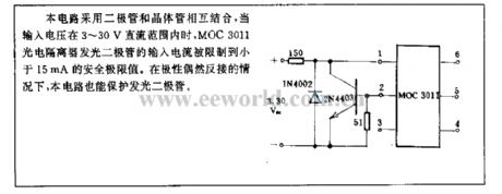
This circuit combines diode with transistor, when the input voltage is in the range of DC 3~30V, the input current of MOC3011 photoelectric isolator LED is limited in the security limit value 15mA. In the case of polarity reverse connection occasionally, this circuit also can protect LED. (View)
View full Circuit Diagram | Comments | Reading(590)
Solid laser range finder reception circuit
Published:2011/4/24 7:29:00 Author:Nicole | Keyword: laser range finder

The amplification of this circuit is about 12000 times, the bandwidth is 0.5~14MHz, the input resistance is 700Ω, the output resistance is 35Ω(measured with 5MHz), the output noise level is 0.6~0.8V.
In figure, T1, T2 are direct coupling amplifier, they are connected into parallel current negative feedback. Zener diode 2CW11 improves T2 emitter level, it ensures the level configuration relationship between T1, T2.
T3, T4 is a pair of direct coupled feedback, it belongs to voltage series negative feedback, reducing the output resistance to improve the transmission coefficient of low load resistance. (View)
View full Circuit Diagram | Comments | Reading(2711)
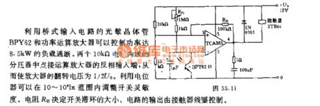
Day and night optical control switch circuit with 10-10LX light intensity
Published:2011/4/22 22:21:00 Author:Nicole | Keyword: optical control switch, 10-10LX light intensity
(View)
View full Circuit Diagram | Comments | Reading(529)
Light intensity control alarm circuit
Published:2011/4/22 23:05:00 Author:Nicole | Keyword: light intensity, alarm
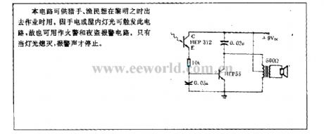
This circuit is used by hunters and fishermen when they want to work at daylight. Because the flashlight or indoor light can trigger this circuit, so it also can be used as fire alarm and burglary alarm circuit. Only the light turns off, the alarm voice will stop. (View)
View full Circuit Diagram | Comments | Reading(611)
Antivibration Circuit Equipped NAND Gate
Published:2011/4/25 23:57:00 Author:Joyce | Keyword: Antivibration, Equipped with, NAND Gate

Dither signals may be arised when the mechanical switch of the keyboard is turned into digital signals,which would lead to incorrect operation , in this case, you can refer to this circuit. Under the condition of using irregular flip-flop (Q1 = Q2 = 0),you can connect a piece of ground wire with the rest of the NAND gates.
(View)
View full Circuit Diagram | Comments | Reading(469)
Separately excited switching regulated power supply circuit 3
Published:2011/4/25 21:17:00 Author:May | Keyword: Separately excited, switching, regulated power supply
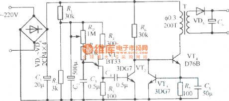
The diagram is separately excited switching regulated power supply circuit which using self-excited multivibrator as pulse generator. In the diagram, VTl is switching tube; VT2, VT3 is pushing tube; VT4 is emitter follower. Separately excited oscillation circuit is self-excited multivibrator consists of VT5, VT6, C2, C3, R3, R4, etc. VT7, VT8 forms emitter-coupled differential amplifier and it uses as error amplifier. Sampling circuit consists of resistor R7, R8 and potentiometer R9 in series. Reference voltage source circuit is composed of diode VD4 and R5. Diode VDl, VD2 is used to prevent the push tube VT2, VT3 emitter breakdown by reverse voltage. VD3 is freewheeling diode; L is energy storage inductor.
Switching regulator's turn-on and cut-off is overturned by multivibrator and controlled by emitter follower VT4.The time of multivibrator’s reversal is determined by error amplifier. That is to say, the reversal time of VT5 from cut off to turned off is determined by the charging current of V8 to C3. If the current of VT is larger, the cut off time of VT5 is longer. (View)
View full Circuit Diagram | Comments | Reading(880)
Metal detector 1
Published:2011/4/26 4:38:00 Author:Ecco | Keyword: Metal detector

The working principle.The metal detector circuit consists of a fixed frequency oscillator, mixer, detector, detection oscillator and power amplifier circuit, it is shown as Figure 8-67.
Fixed frequency oscillator circuit consists of ceramic filters ZC, transistors Vl and resistors Rl-R4, capacitors C2 and so on. Mixer consists of the mixer tube V2 and capacitor C3, resistors R5-R8. The detector is composed of diodes VDl, VD2, capacitors C8-Cl2 and resistors Rl2, potentiometer RP and other components. Detected oscillator is composed of transistor V3, inductance coil L, capacitors C4-C7, Clg, and resistors R9-Rll. The audio amplifier is composed of power amplifier integrated circuit IC, resistors R13-Rl5, capacitors C13-C18 and speaker BL.
RI-Rl5 use 1/4W carbon film resistors or metal film resistors. Cl and C14, Cl5 select electrolytic capacitors with voltage in 16V; C2-C4, C7-C13 and C16 C18 select monolithic capacitors; C5 and C6 select high-frequency ceramic capacitors; Cl9 uses small polyester film or mica trimmer capacitors. VDl and VD2 select 2AP9 common type germanium diode. Vl-V3 uses S9018 or BM94 silicon NPN transistor. IC uses TDA2822 audio power amplifier integrated circuit.
(View)
View full Circuit Diagram | Comments | Reading(2182)
PFS-4091 High sensitive infrared receiving device the internal circuit diagram
Published:2011/4/24 4:06:00 Author:Rebekka | Keyword: infrared receiving device


(View)
View full Circuit Diagram | Comments | Reading(911)
Metal detector 2
Published:2011/4/26 4:20:00 Author:Ecco | Keyword: Metal detector

This metal detectors described in the example can be used to detect metal objects with high permeable magnetic substances. The working principle.The metal detector circuit is composed of the power circuit, sine wave oscillator, PLL phase-locked loop circuit and hybrid amplification circuit, it is shown in Figure 8-68.
Power circuit is composed of the battery GBl, GB2, filter capacitor Cl, C2, and the power switch S (Sa, Sb). Sinusoidal oscillator circuit consists of transistors Vl, detecting coil L, capacitor C3-C5 and resistors Rl, R2. PLL circuit is composed of dual time-base integrated circuit and resistors R3, potentiometers RPI, capacitors C6-C8. The hybrid amplification circuit is composed of the transistors V2, V3, resistors R4-R6, potentiometer RP2 and ammeter PA.
Rl-R6 use l/8W or 1/4W carbon film resistors. RPl uses multi-turn precision potentiometer; RP2 uses general lap synthetic membranes potentiometer. Cl and C2 select electrolytic capacitors with voltage in 16V; C3-C5 and C8 select monolithic capacitors; C6 and C7 select high-frequency ceramic capacitors. (View)
View full Circuit Diagram | Comments | Reading(5877)
Composed of MC145026 and 145027 infrared transmitter and receiver circuit diagram
Published:2011/4/22 3:15:00 Author:Rebekka | Keyword: infrared transmitter and receiver


MC145026/145027 are dedicated remote control encoder / decoder ICs. They can achieve binary or ternary addressing(ternary makes encoding / decoding become the largest number). Both using in conjunction can be used for infrared, radio frequency, ultrasonic transmission media remote control of different transmit / receive circuit.
MC145026 pin diagram form
MC145027 pin diagram form
Infrared transmitter circuit composed of MC145026
Infrared receiver circuit composed of MC145027.
(View)
View full Circuit Diagram | Comments | Reading(2560)
Toyota Coaster bus engine circuit diagram 1
Published:2011/4/26 20:54:00 Author:Rebekka | Keyword: Toyota Coaster bus, engine

Toyota Coaster bus engine circuit diagram is shown as above. (View)
View full Circuit Diagram | Comments | Reading(971)
DUT07 AC distribution box electrical schematic diagram
Published:2011/4/21 21:42:00 Author:muriel | Keyword: distribution box, electrical schematic diagram

DUT07 HF switch power supply system is based on the DZW75-48/50(50II) type rectifier module with JP50-50II) type AC distribution box. As shown in the figure is the schematic diagram of the P50-AC distribution box. (View)
View full Circuit Diagram | Comments | Reading(1816)
SCR AC switch
Published:2011/4/22 18:57:00 Author:Nicole | Keyword: SCR, switch
Although bidirectional SCR is suitable for AC load switch, it should adopt unidirectional SCR when the work voltage is high or the load current is large. In figure, the circuit SCR gate is controlled by small transformer output rectified voltage loop directly. The advantage of using DC trigger is: it can connect high resistance load circuit.
Technical data of this circuit: work voltage: 380V; load resistance: 500Ω~80kΩ; control current: about 6.5mA.
Transformer data: the number of windings n1: 7400 turns, 0.08mm enameled copper wire; the number of windings n2, n3: 230 turns, 0.25mm enameled copper wire. (View)
View full Circuit Diagram | Comments | Reading(670)
Photoelectric ignition circuit
Published:2011/4/22 20:36:00 Author:Nicole | Keyword: photoelectric ignition circuit
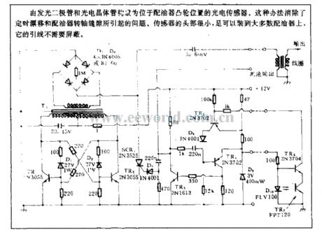
Located at re-greasing distributor cam, the photoelectric sensor is composed of LED and phototransistor. It can eliminate the problems produced by timing drift and re-greasing distributor transfer oil gap. The head of sensor is very small, it can be fixed in majority of re-greasing distributor, its lead wire has no need of shielding. (View)
View full Circuit Diagram | Comments | Reading(961)
| Pages:1998/2234 At 2019811982198319841985198619871988198919901991199219931994199519961997199819992000Under 20 |
Circuit Categories
power supply circuit
Amplifier Circuit
Basic Circuit
LED and Light Circuit
Sensor Circuit
Signal Processing
Electrical Equipment Circuit
Control Circuit
Remote Control Circuit
A/D-D/A Converter Circuit
Audio Circuit
Measuring and Test Circuit
Communication Circuit
Computer-Related Circuit
555 Circuit
Automotive Circuit
Repairing Circuit