
Circuit Diagram
Index 1883
FR9600-the Microcomputer Intergrated Circuit of Communication Single Doors
Published:2011/5/12 19:58:00 Author:Borg | Keyword: Microcomputer, Intergrated Circuit, Communication Single Doors

FR96 (View)
View full Circuit Diagram | Comments | Reading(526)
Low level signal isolation amplifier circuit diagram
Published:2011/5/12 1:45:00 Author:Ecco | Keyword: Low level signal, isolation, amplifier

Low level signal isolation amplifier circuit diagram is shown as the chart.
(View)
View full Circuit Diagram | Comments | Reading(900)
SF220-550 hood monolithic microcomputer integrated circuit diagram
Published:2011/5/12 2:00:00 Author:Ecco | Keyword: hood , monolithic , microcomputer , integrated circuit


SF220-550 is the hood monolithic microcomputer integrated circuit, it is widely used in many brands of smoke hoods. SF220-550 IC uses the 24-pin dual in-line package, the typical application circuit is shown as the chart, the pin functions and data are listed in Table.
(View)
View full Circuit Diagram | Comments | Reading(787)
LED digital display mode circuit diagram
Published:2011/5/12 1:42:00 Author:Ecco | Keyword: LED , digital display, mode

LED digital display mode is shown in Table 28-2. 7 LEDs are made in strip type, they are respectively a, b, c, d, e, f, g and on behalf of digital strokes, selected making strokes emit light, so that you can form ten 0-9 digital code. Another light-emitting diode is a decimal point DP.
The modes of LED digital display are shown as the chart.
(View)
View full Circuit Diagram | Comments | Reading(626)
The level test circuit diagram composed of TTL NOR gate connecting as inverter
Published:2011/5/12 1:59:00 Author:Ecco | Keyword: level , test, TTL, NOR gate , connecting , inverter
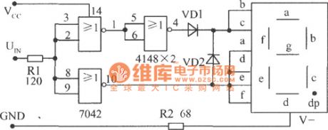
TTL NOR gate is connected as inverter, and it is equipped with common cathode LED,the high level shows q, low level displays 0. The circuit is shown in Fig.
The level test circuit diagram composed of TTL NOR gate connecting as inverter and matching common cathode LED (View)
View full Circuit Diagram | Comments | Reading(713)
Two-channel audio power amplifier integrated circuit diagram
Published:2011/5/12 1:55:00 Author:Ecco | Keyword: Two-channel , audio , power amplifier, integrated circuit

TDA2007 is a dual audio power amplifier integrated circuit produced by Philips, which is widely used in television audio, home audio, multimedia audio, computer audio, car audio and so on. 1.The featuresand functionsThe internal circuit of TDA2007 integrated circuit is mainly composed of two identical audio power amplifier circuit, overheat and over current, short circuit protection circuit. 2. Pin functions and data TDA2007 IC uses 9-pin single in-line package, the pin functions and data are listed in Table 1. Table 1 shows TDA2007 integrated circuit pin functions and data.
(View)
View full Circuit Diagram | Comments | Reading(672)
TC9311F-014 logic control system IC chart
Published:2011/5/12 1:55:00 Author:Ecco | Keyword: logic control system , IC

TC9311F-014 is the control system logic IC produced by Toshiba company, :It is widely applied to Ikaiwa, Toshiba and domestic walkmen and repetition machines.
TC9311F-014 IC uses a dual flat package with 20 feet, the pin functions and data are listed in Table 1. Table 1 shows TC9311F-014 IC pin functions and data.
(View)
View full Circuit Diagram | Comments | Reading(1777)
Mitsubishi Pajero light sport utility vehicle defrost air conditioning circuit diagram
Published:2011/5/8 11:34:00 Author:Rebekka | Keyword: Mitsubishi Pajero , light sport utility vehicle

31 defroster switch; 32 defrost relay; 33 defrost indicator; 34 defroster; 35 resistor; 36 blower relay; 37 blast motor; 38 blower switch; 39 air conditioning switch; 40 air conditioning controller; 41 air temperature sensor; 42 inlet temperature sensor; 43 dual pressure switch (LON-OFF: O · 2MPa, OFF-ON: O · 23MPa; H: ON-OFF : 3.8 MPa, OFF-ON: 3.2 MPa); 4 air conditioning compressor relay; 45 condenser fan motor relay; 46 increased idle speed solenoid valve; 47 electromagnetic clutch; 48 engine temperature switch; 49 condenser fan motor; 68 the fire switch; 1 battery; 172 headlamp washer relay. (View)
View full Circuit Diagram | Comments | Reading(3275)
Dynamic scanning display circuit diagram
Published:2011/5/12 1:54:00 Author:Ecco | Keyword: Dynamic, scanning , display
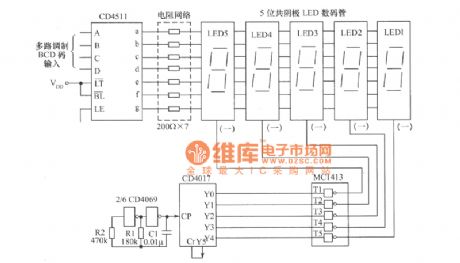
The dynamic scanning display circuit shown as the chart is composed of the decoder CD4511 and beat generator drive CD4017, 7 road Darlington drive MC1413. LED1 ~ LED5 are five common cathode LED displays.
(View)
View full Circuit Diagram | Comments | Reading(1521)
The electrical principle circuit diagram of soymilk
Published:2011/5/12 1:52:00 Author:Ecco | Keyword: electrical principle circuit , soymilk

View full Circuit Diagram | Comments | Reading(725)
PCA8515 character formation integrated circuit diagram
Published:2011/5/12 1:45:00 Author:Ecco | Keyword: character , formation , integrated circuit


PCA8515 is the character formation integrated circuit produced by Philips, it is widely used in large screen color TV, such as Changhong color TV projection series. 1. Features of functionsPCA8515 ICcontains display with horizontal and vertical positioning pulse processing circuit, the character clock circuit, I2C bus interface circuit, reset circuit, serial interface circuit, and other auxiliary functions circuit. The block diagram of the circuit is shown as the chart. 2. Pin functions and data PCA8515 uses the hundred inserting package with 24 pin in dual rows, the pin functions and data are listed in Table.
(View)
View full Circuit Diagram | Comments | Reading(617)
10 LED level display circuit diagram
Published:2011/5/12 1:43:00 Author:Ecco | Keyword: 10, LED, level , display

10 LED level display circuit composed of 2 pieces BA6104 5-bit LED level meter driver integrated circuit
10 LED level display circuit composed of 2 pieces BA6104 5-bit LED level meter driver integrated circuitis shown in Figure, regulating Vref of pin 7 in IC1, the L1 ~ L5 will be lit; adjusting the Vref of pin 7 in IC2 will turn on the L1 ~ IC2 L5, the light voltage is 2 times of IC1, luminous order is L1 ~ L5 in IC1, L1 ~ L5 in IC2.
(View)
View full Circuit Diagram | Comments | Reading(1712)
BL6124 5-bit LED level meter driver IC basic application circuit
Published:2011/5/12 1:43:00 Author:Ecco | Keyword: 5-bit, LED , level meter, driver , IC, basic application

10 LED level display circuit is composed of two pieces of BA6104.LED current limiting circuit is used to limit the LED current by connecting a resistor in parallel or series next to LED, it is shown as Figure (a), (b). When working voltageis higher than 9V, it could add a shunt resistor beside the LED current end, while the circuit with different specific Vcc values are shown in Fig. (View)
View full Circuit Diagram | Comments | Reading(1708)
S13120C 12V V terminal voltage regulator integrated circuit diagram
Published:2011/5/12 1:44:00 Author:Ecco | Keyword: 12V , V terminal, voltage regulator, integrated circuit
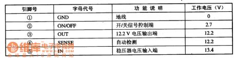
S13120C is the 12V V terminal voltage regulator integrated circuit produced by the micro-systems in the United States, it is widely used in DVD players, televisions, computer monitors, sound system and various kinds of small household appliances in the voltage regulator circuit. 1. Features of functionS13120C IC contains 12V regulated power supply circuit, power supply on / off control circuit, automatic detection circuit and some other ancillary features circuit.2. Pin functions and dataS13120C integrated circuit uses separate 5-pin package, the pin functions and data are listed in Table. S13120C IC pin functions and data
(View)
View full Circuit Diagram | Comments | Reading(708)
LED digital display internal circuit diagram
Published:2011/5/12 1:42:00 Author:Ecco | Keyword: LED, digital display , internal circuit

The most LEDs used in digital display are red, and they are divided into two parts of unit and sub-units. The internal circuit of unit LED digital display is shown in Figure 28-5, which is divided into common anode and cathode connection types, and they are representing the strokes of the a-g LED positive or negative ends being leaded by pins, which DP feet is on behalf of the decimal point.
LED digital display internal circuit diagram is shown as the chart. (View)
View full Circuit Diagram | Comments | Reading(594)
Shanghai GM Regal 2.0L intake temperature sensor connector terminal and connecting circuit diagram
Published:2011/5/12 1:23:00 Author:Nicole | Keyword: Shanghai GM Regal, intake temperature sensor, connector terminal

Shanghai GM Regal 2.0L intake manifold absolute pressure sensor and intake temperature sensor connector terminal and connecting circuit diagram
The intake manifold absolute pressure sensor and the intake temperature sensor are made into one, they are fixed to exhaust manifold. The connecting circuit of these two sensors connector terminal and electronic control unit is shown as below.
Intake temperature sensor is a negative temperature coefficient thermal resistor, the motor electronic control unit provides 5V power supply by its internal resistance.
When it is idle speed(high vacuum), the intake manifold absolute pressure sensor MAP output singal is lower than 2.0V; when the ignition switch is turned on and the motor does not run, the throttles are all open(low vacuum), it is higher than 4.0V.
(View)
View full Circuit Diagram | Comments | Reading(456)
Pulse delay circuit circuit diagram
Published:2011/5/12 6:23:00 Author:Rebekka | Keyword: Pulse delay circuit

If you need to delay longer than the input pulse width of the pulse delay circuit, you can use pulse delay circuit composed of the NAND gate and single-shot. Its composition is shown in the figure. (View)
View full Circuit Diagram | Comments | Reading(2408)
Hydraulic slipway PWM microcomputer control drive circuit diagram
Published:2011/5/12 20:47:00 Author:Nicole | Keyword: Hydraulic slipway, PWM, microcomputer, control drive

View full Circuit Diagram | Comments | Reading(557)
High power IGBT high frequency inverter electric welding machine circuit diagram
Published:2011/5/12 20:52:00 Author:Nicole | Keyword: IGBT, high frequency inverter, electric welding machine

View full Circuit Diagram | Comments | Reading(9172)
UC3637 two phase stepping motor driver drive circuit diagram
Published:2011/5/12 20:58:00 Author:Nicole | Keyword: two phase, stepping motor, driver drive

View full Circuit Diagram | Comments | Reading(1259)
| Pages:1883/2234 At 2018811882188318841885188618871888188918901891189218931894189518961897189818991900Under 20 |
Circuit Categories
power supply circuit
Amplifier Circuit
Basic Circuit
LED and Light Circuit
Sensor Circuit
Signal Processing
Electrical Equipment Circuit
Control Circuit
Remote Control Circuit
A/D-D/A Converter Circuit
Audio Circuit
Measuring and Test Circuit
Communication Circuit
Computer-Related Circuit
555 Circuit
Automotive Circuit
Repairing Circuit