
Circuit Diagram
Index 168
Proximity Switch
Published:2013/2/24 21:01:00 Author:muriel | Keyword: Proximity Switch
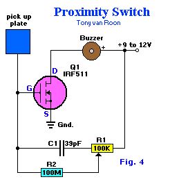
Proximity Switch. This design takes advantage of the ultra-high input impedance and power-handling capabilities of the IRF511 to make a simple, but sensitive, proximity sensor and alarm driver circuit.A 3x3-inch piece of circuit board (or similar size metal object), which functions as the pick-up sensor, is connected to the gate of Q1. A 100 MegaOhm resistor, R2, isolates Q1's gate from R1, allowing the input impedance to remain very high. If a 100-MegaOhm resistor cannot be located, just tie 5 22-MegaOhm resistors in series and use that combination for R2. In fact, R2 can be made even higher in value for added sensitivity.Potentiometer R1 is adjusted to a point where the piezo buzzer just begins to sound off and then carefully backed off to the point where the sound ceases. Experimenting with the setting of R1 will help in obtainin the best sensitivity adjustment for the circuit. Potentiometer R1 may be set to a point where the pick-up must be contacted to set of the alarm sounder. A relay or other current-hungry component can take the place of the piezo sounder to control almost any external circuit
(View)
View full Circuit Diagram | Comments | Reading(0)
Incandescent Lamp Flasher
Published:2013/2/24 21:00:00 Author:muriel | Keyword: Incandescent Lamp Flasher
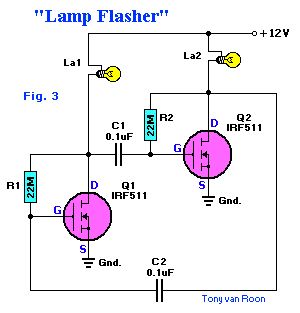
Incandescent Lamp Flasher using two IRF511 HexFets which are configured as a simple astable multivibrator to alternately switch the two lamps, La1 and La2, on and off. The R & C values given set the flash rate to about 1/3 Hz. By varying either the resistor or capacitor values almost any flash rate can be obtainded. Increase either C1 and C2, or R1 and R2, and the flash rate slows. Decrease them and the rate increases.Unlike most semiconductor devices, the power MosFet can be paralleled, without special current-sharing components, to control larger load currents. That can be an important feature when the device is used to turn on incandescent lamps, because the lamp's cold resistance is much lower than the normal operating resistance.A typical #1815 12 to 14-volt lamp measures 6 ohms cold. When 12 volts is applied, the initial current drawn is 2 amps. The same lamp, when operating at 12 volts, requires only about 200mA. The hot resistance figures out to be ten times its cold resistance, or 60 ohms. That tidbit should be considered when picking any semiconductor device to control an incandescent lamp. (View)
View full Circuit Diagram | Comments | Reading(2245)
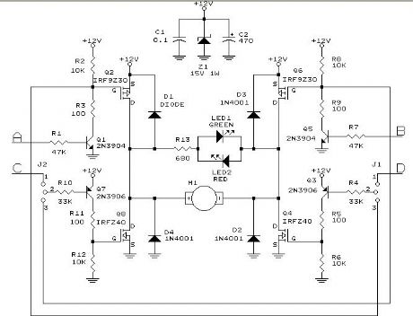
Relay-Controller
Published:2013/2/24 21:00:00 Author:muriel | Keyword: Relay-Controller
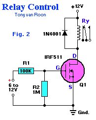
Relay-Controller. With zero-gate bias applied, Q1 acts lilke an open switch, but when a DC voltage greater than 5 volts is applied to the input of the circuit, Q1 turns on, completing the relay circuits and therby activating the relay coil.The input bias current required to turn on Q1 and operate the relay is less than 10 uA (microAmps), which is about 1/1,000,000 of the current required to bias the popular 2N3055 power transistor to operate the same relay.R1 protects whatever's driving the MOSFET and filters against very short transients--together with (mainly) the gatet capacitance. The MOSFET doesn't need protection (as long as it never sees more than 12V), as its gate is insulated. For faster switching, use 100 ohm rather than 100K.R2 is only needed if the circuit driving it doesn't return to ground - to make sure it turns off. For fast OFF times, use as low an impedance as the driving circuit can safely handle.If driven from a (weak) CMOS gate from the 4K series (e.g. a 4093) as a Vdd of 12V, you could use 1K (or even lower) for R1 - and leave out R2 as the gates output goes to ground anyway. (View)
View full Circuit Diagram | Comments | Reading(1525)
Class-A Audio Amplifier
Published:2013/2/24 20:59:00 Author:muriel | Keyword: Class-A, Audio Amplifier
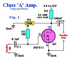
Class-A Audio Amplifier. With zero gate bias applied, Q1 is like switch in the off state, so no current flows through the load resistor R2. Ideally speaking, the voltage across Q1 and the load resistor should be equal for class-A operation. A 100K potentiometer (R3) and a 1-MegaOhm fixed resistor (R1) maker up a simple adjustable gate-bias circuit. Plase a voltmeter between the Drain (D) of Q1 and the circuit ground, and adjust R3 for a meter reading of half the power supply voltage.Almost any resistor value can be used for R2 as long as the maximum current and power ratings of the FET are not exceeded. A resistor value between 22 and 100 ohms is a good choice for experimenting. At high currents, a suitable heat sink should be used. (View)
View full Circuit Diagram | Comments | Reading(3715)
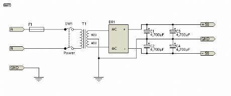
Power Supply Circuit Diagram 4
Published:2013/2/24 20:58:00 Author:muriel | Keyword: Power Supply
View full Circuit Diagram | Comments | Reading(762)
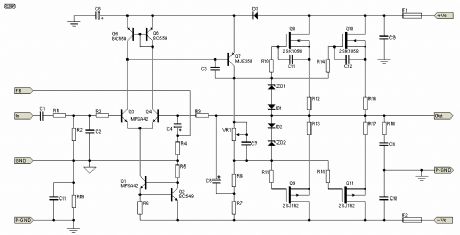
High Power, High Fidelity Lateral MOSFET Power Amplifier 2
Published:2013/2/24 20:57:00 Author:muriel | Keyword: High Power, High Fidelity, Lateral MOSFET , Power Amplifier
View full Circuit Diagram | Comments | Reading(4750)
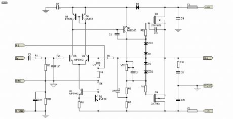
High Power, High Fidelity Lateral MOSFET Power Amplifier
Published:2013/2/24 20:56:00 Author:muriel | Keyword: High Power, High Fidelity, Lateral MOSFET , Power Amplifier
View full Circuit Diagram | Comments | Reading(3312)
The Using MOSFETS Website
Published:2013/2/24 20:55:00 Author:muriel | Keyword: MOSFETS Website
View full Circuit Diagram | Comments | Reading(589)
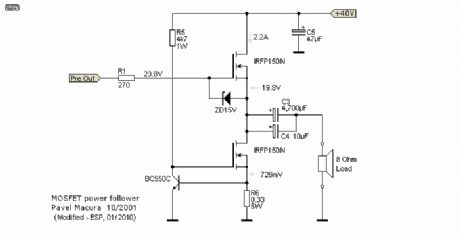
Pavel's Latest Version Direct Coupled Power Follower
Published:2013/2/24 20:53:00 Author:muriel | Keyword: Latest Version , Direct Coupled, Power Follower
View full Circuit Diagram | Comments | Reading(0)
Direct Coupled Power Follower Using MOSFET Current Source
Published:2013/2/24 20:53:00 Author:muriel | Keyword: Direct Coupled, Power Follower, MOSFET, Current Source
View full Circuit Diagram | Comments | Reading(1981)
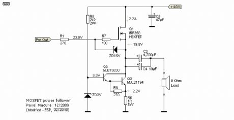
Power Follower Modified for Direct Coupling
Published:2013/2/24 20:52:00 Author:muriel | Keyword: Power Follower , Direct Coupling
View full Circuit Diagram | Comments | Reading(712)
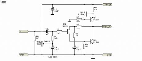
DoZ Preamp as Driver
Published:2013/2/24 20:51:00 Author:muriel | Keyword: DoZ Preamp, Driver
View full Circuit Diagram | Comments | Reading(2527)
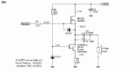
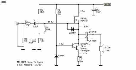
MOSFET POWER FOLLOWER
Published:2013/2/24 20:51:00 Author:muriel | Keyword: MOSFET POWER FOLLOWER
View full Circuit Diagram | Comments | Reading(1247)
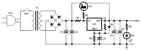
Regulated Power Supply Circuit diagram 1
Published:2013/2/24 20:49:00 Author:muriel | Keyword: Regulated, Power Supply
View full Circuit Diagram | Comments | Reading(1255)
Preamps Circuit diagram
Published:2013/2/24 20:49:00 Author:muriel | Keyword: Preamps Circuit

View full Circuit Diagram | Comments | Reading(1456)
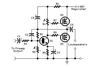
Mini-MosFet Audio Amplifiers
Published:2013/2/24 20:48:00 Author:muriel | Keyword: Mini-MosFet, Audio Amplifiers
View full Circuit Diagram | Comments | Reading(2165)
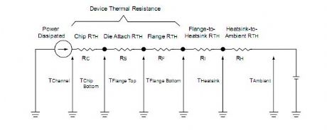
Thermal Circuit
Published:2013/2/24 20:47:00 Author:muriel | Keyword: Thermal Circuit
View full Circuit Diagram | Comments | Reading(583)
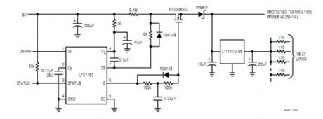
SCSI Termination Power Protection
Published:2013/2/24 20:46:00 Author:muriel | Keyword: SCSI Termination, Power Protection
View full Circuit Diagram | Comments | Reading(692)
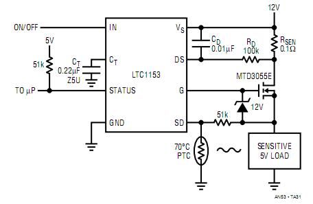
5V/1A Circuit Breaker with Thermal Shutdown
Published:2013/2/24 20:45:00 Author:muriel | Keyword: 5V, 1A , Circuit Breaker, Thermal Shutdown
View full Circuit Diagram | Comments | Reading(1120)
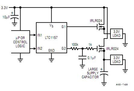
Dual High Side 3.3V Switch
Published:2013/2/24 20:44:00 Author:muriel | Keyword: Dual , High Side , 3.3V , Switch
View full Circuit Diagram | Comments | Reading(760)
| Pages:168/2234 At 20161162163164165166167168169170171172173174175176177178179180Under 20 |
Circuit Categories
power supply circuit
Amplifier Circuit
Basic Circuit
LED and Light Circuit
Sensor Circuit
Signal Processing
Electrical Equipment Circuit
Control Circuit
Remote Control Circuit
A/D-D/A Converter Circuit
Audio Circuit
Measuring and Test Circuit
Communication Circuit
Computer-Related Circuit
555 Circuit
Automotive Circuit
Repairing Circuit