Amplifier Circuit
Class-A Audio Amplifier
Published:2013/2/24 20:59:00 Author:muriel | Keyword: Class-A, Audio Amplifier | From:SeekIC

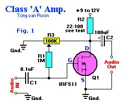
Class-A Audio Amplifier. With zero gate bias applied, Q1 is like switch in the off state, so no current flows through the load resistor R2. Ideally speaking, the voltage across Q1 and the load resistor should be equal for class-A operation. A 100K potentiometer (R3) and a 1-MegaOhm fixed resistor (R1) maker up a simple adjustable gate-bias circuit. Plase a voltmeter between the Drain (D) of Q1 and the circuit ground, and adjust R3 for a meter reading of half the power supply voltage.Almost any resistor value can be used for R2 as long as the maximum current and power ratings of the FET are not exceeded. A resistor value between 22 and 100 ohms is a good choice for experimenting. At high currents, a suitable heat sink should be used.
Reprinted Url Of This Article:
http://www.seekic.com/circuit_diagram/Amplifier_Circuit/Class_A_Audio_Amplifier.html
Print this Page | Comments | Reading(3)

Article Categories
power supply circuit
Amplifier Circuit
Basic Circuit
LED and Light Circuit
Sensor Circuit
Signal Processing
Electrical Equipment Circuit
Control Circuit
Remote Control Circuit
A/D-D/A Converter Circuit
Audio Circuit
Measuring and Test Circuit
Communication Circuit
Computer-Related Circuit
555 Circuit
Automotive Circuit
Repairing Circuit
Code: