Control Circuit
Relay-Controller
Published:2013/2/24 21:00:00 Author:muriel | Keyword: Relay-Controller | From:SeekIC

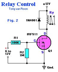
Relay-Controller. With zero-gate bias applied, Q1 acts lilke an open switch, but when a DC voltage greater than 5 volts is applied to the input of the circuit, Q1 turns on, completing the relay circuits and therby activating the relay coil.The input bias current required to turn on Q1 and operate the relay is less than 10 uA (microAmps), which is about 1/1,000,000 of the current required to bias the popular 2N3055 power transistor to operate the same relay.R1 protects whatever's driving the MOSFET and filters against very short transients--together with (mainly) the gatet capacitance. The MOSFET doesn't need protection (as long as it never sees more than 12V), as its gate is insulated. For faster switching, use 100 ohm rather than 100K.R2 is only needed if the circuit driving it doesn't return to ground - to make sure it turns off. For fast OFF times, use as low an impedance as the driving circuit can safely handle.If driven from a (weak) CMOS gate from the 4K series (e.g. a 4093) as a Vdd of 12V, you could use 1K (or even lower) for R1 - and leave out R2 as the gates output goes to ground anyway.
Reprinted Url Of This Article:
http://www.seekic.com/circuit_diagram/Control_Circuit/Relay_Controller.html
Print this Page | Comments | Reading(3)

Article Categories
power supply circuit
Amplifier Circuit
Basic Circuit
LED and Light Circuit
Sensor Circuit
Signal Processing
Electrical Equipment Circuit
Control Circuit
Remote Control Circuit
A/D-D/A Converter Circuit
Audio Circuit
Measuring and Test Circuit
Communication Circuit
Computer-Related Circuit
555 Circuit
Automotive Circuit
Repairing Circuit
Code: