
Circuit Diagram
Index 175
CodeLock AVR electronic combination lock 4
Published:2013/2/18 21:04:00 Author:muriel | Keyword: CodeLock , AVR , electronic combination lock
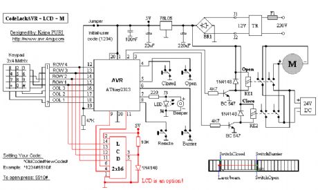
View full Circuit Diagram | Comments | Reading(1240)
CodeLock AVR electronic combination lock 3
Published:2013/2/18 21:03:00 Author:muriel | Keyword: CodeLock , AVR , electronic combination lock
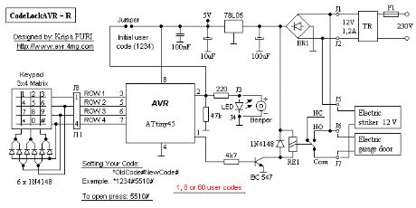
View full Circuit Diagram | Comments | Reading(665)
CodeLock AVR electronic combination lock 2
Published:2013/2/18 21:03:00 Author:muriel | Keyword: CodeLock, AVR , electronic combination lock
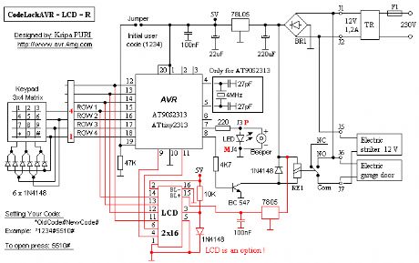
View full Circuit Diagram | Comments | Reading(646)
CodeLock AVR electronic combination lock 1
Published:2013/2/18 21:02:00 Author:muriel | Keyword: CodeLock , AVR, electronic combination lock
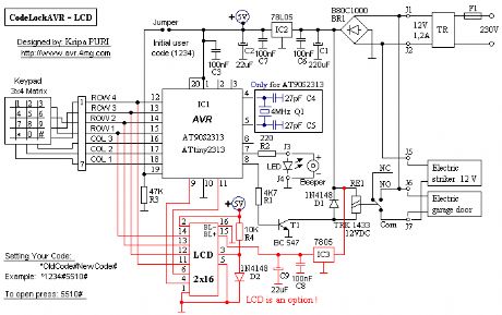
View full Circuit Diagram | Comments | Reading(664)
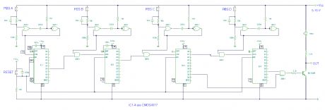
Simple electronic combination lock
Published:2013/2/18 21:01:00 Author:muriel | Keyword: Simple electronic , combination lock
View full Circuit Diagram | Comments | Reading(963)
Electronic Combination Lock 1
Published:2013/2/18 21:00:00 Author:muriel | Keyword: Electronic Combination Lock
View full Circuit Diagram | Comments | Reading(598)
Electronic Card-Lock System
Published:2013/2/18 20:59:00 Author:muriel | Keyword: Electronic Card-Lock System
View full Circuit Diagram | Comments | Reading(2572)
Digital Electronic Lock circuit
Published:2013/2/18 20:58:00 Author:muriel | Keyword: Digital Electronic , Lock circuit
View full Circuit Diagram | Comments | Reading(554)
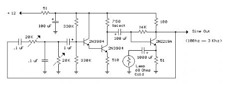
Low Frequency Wien Bridge RC Sinewave Oscillator 3
Published:2013/2/18 20:57:00 Author:muriel | Keyword: Low Frequency, Wien Bridge , RC Sinewave, Oscillator
View full Circuit Diagram | Comments | Reading(740)
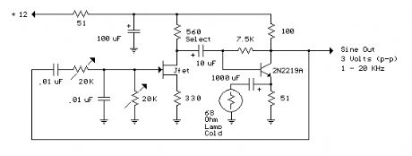
Low Frequency Wien Bridge RC Sinewave Oscillator 2
Published:2013/2/18 20:57:00 Author:muriel | Keyword: Low Frequency, Wien Bridge , RC Sinewave , Oscillator
View full Circuit Diagram | Comments | Reading(592)
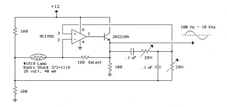
Low Frequency Wien Bridge RC Sinewave Oscillator 1
Published:2013/2/18 20:56:00 Author:muriel | Keyword: Low Frequency , Wien Bridge , RC Sinewave , Oscillator
View full Circuit Diagram | Comments | Reading(601)
Electronic combination lock based on PIC 2
Published:2013/2/18 20:55:00 Author:muriel | Keyword: Electronic combination lock, PIC
View full Circuit Diagram | Comments | Reading(882)
Electronic combination lock based on PIC
Published:2013/2/18 20:54:00 Author:muriel | Keyword: Electronic combination lock, PIC
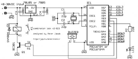
View full Circuit Diagram | Comments | Reading(984)
Digital Combination Lock circuit
Published:2013/2/18 20:53:00 Author:muriel | Keyword: Digital Combination, Lock circuit
View full Circuit Diagram | Comments | Reading(675)
Door lock opener
Published:2013/2/18 20:52:00 Author:muriel | Keyword: Door lock, opener
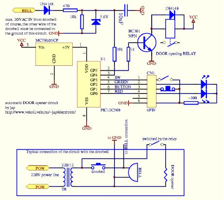
View full Circuit Diagram | Comments | Reading(721)
Pulse oscillator with adjustable duty cycle and frequency
Published:2013/2/18 2:11:00 Author:Ecco | Keyword: Pulse oscillator, adjustable duty cycle , frequency

Pulse oscillator with adjustable duty cycle and frequency is shown as figure.
(View)
View full Circuit Diagram | Comments | Reading(1440)
High-side current monitoring circuit with INA168
Published:2013/2/18 2:07:00 Author:Ecco | Keyword: High-side, current monitoring
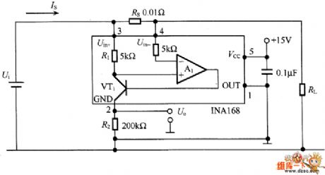
In the measurement of changed supply current, the return line of the power -side is grounded, sometimes it can not be connected to shunt resistor between the casing and the rack. INA168 is a current detecting circuit ASIC, the indicators are as following: The power supply voltage is 30 ~~ 60V, and the detected current is at least 10A, then the detection output voltage is 4V, the accuracy is less than 1%.
(View)
View full Circuit Diagram | Comments | Reading(1571)
Light control energy-saving lamp (1) circuit
Published:2013/2/17 20:42:00 Author:Ecco | Keyword: Light control, energy-saving lamp
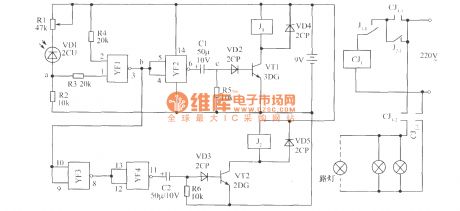
The working principle of the circuit is shown as figure, it is composed of the photoelectric conversion part, NAND gate, differential circuit and control circuit. When there is light, the photosensitive diode VD1 gets conduction, the potential of point A reaches the NAND gate YF1 door level, the output terminal of point b shows low potential, YF2 outputs the high potential, C1 and R5 form a differential circuit which outputs positive spikes at the point C, so BG1 gets conduction, J1 is instantaneously pulled ( then release ). Normally closed contact J1-1 is disconnected, CJ1 loses power and releases, the self-protection contact CJ1-1 disconnects, then the light is off.
(View)
View full Circuit Diagram | Comments | Reading(1196)
Multi-channel laser burglar alarm circuit
Published:2013/2/17 21:00:00 Author:Ecco | Keyword: Multi-channel laser, burglar alarm
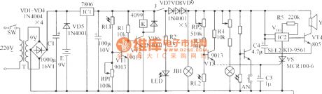
VT1, VT2, RL1, RP1, R1, K and VD6 constitute light control switch, in the daytime, photoresistor RL1 is in a low resistance state, VT1 gets saturated conduction, VT2 is turned off, K relay is not energized, normally open contact J is in a disconnected state, the alarm circuit does not work; at night, RL1 becomes high impedance, VT1 is deadline, VT2 gets saturated conduction, K gets electrical to make J pull in, then the circuit supplies for the whole machine, red light-emitting diode is lit.
(View)
View full Circuit Diagram | Comments | Reading(1175)
Simple analog phase detector circuit diagram
Published:2013/2/18 0:20:00 Author:Ecco | Keyword: Simple analog phase detector
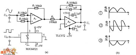
It is composed of an operational amplifier TL072 and analog switch MAX4521, it is applicable to PLL circuit or lock-in amplifier. Supply voltage is ± 5V, the input and output signal level is below ± 4V, and the operating frequency is 10Hz ~~ 100kHz. The UiA and UiB are respectively input sine wave and square wave with the same frequency, square wave's duty cycle is 50 %, the output waveform of A1 is shown in Figure (b).
(View)
View full Circuit Diagram | Comments | Reading(6855)
| Pages:175/2234 At 20161162163164165166167168169170171172173174175176177178179180Under 20 |
Circuit Categories
power supply circuit
Amplifier Circuit
Basic Circuit
LED and Light Circuit
Sensor Circuit
Signal Processing
Electrical Equipment Circuit
Control Circuit
Remote Control Circuit
A/D-D/A Converter Circuit
Audio Circuit
Measuring and Test Circuit
Communication Circuit
Computer-Related Circuit
555 Circuit
Automotive Circuit
Repairing Circuit