Index 183
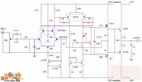
Direct FM Modulation Circuit Diagram composed of Varactor Diode
Published:2011/5/5 9:46:00 Author:Felicity | Keyword: Direct FM Modulation Circuit Diagram, Varactor Diode,
View full Circuit Diagram | Comments | Reading(3718)
TA8141S remote control signal receiving circuit diagram
Published:2011/5/5 3:46:00 Author:Ecco | Keyword: remote control , signal receiving circuit


TA8141S is the remote control signal receiving circuit manufactured by Toshiba in Japan, it is widely used in color television sets, DVD players, car stereos, air conditioners and electric fans and other remote systems. 1. Pin functions and data TA81415 IC uses 9-pin single in-line package, the pin functions and data are listed in Table 1. Table 1 shows TA81415 IC pin functions and data 2. The block circuit diagram and typical application circuit TA81415 block circuit diagram and typical application circuit is shown in Figure 1.
(View)
View full Circuit Diagram | Comments | Reading(568)
Dual-frequency crystal oscillator circuit
Published:2011/5/5 3:37:00 Author:Christina | Keyword: Dual-frequency, crystal, oscillator
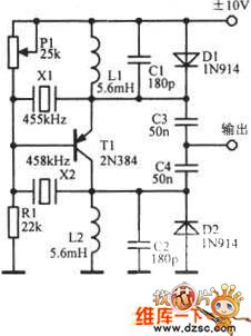
The dual-frequency crystal oscillator circuit is as shown:
(View)
View full Circuit Diagram | Comments | Reading(508)
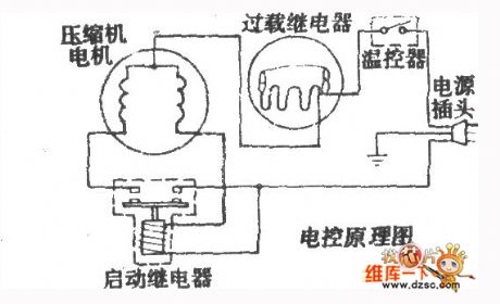
Mitsubishi MRE-2163W/216W-N, MRE-2163G/2163G-N fridge circuit
Published:2011/5/5 3:40:00 Author:Christina | Keyword: Mitsubishi, fridge
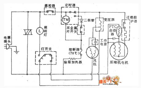
The Mitsubishi MRE-2163W/216W-N, MRE-2163G/2163G-N fridge circuit is as shown:
(View)
View full Circuit Diagram | Comments | Reading(610)
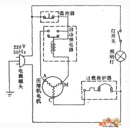
Changqing BCD-205 fridge circuit
Published:2011/5/5 3:33:00 Author:Christina | Keyword: Changqing, fridge
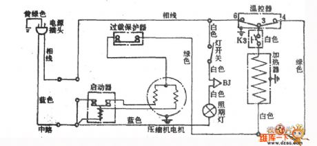
The Changqing BCD-205 fridge circuit is as shown:
(View)
View full Circuit Diagram | Comments | Reading(445)
The different lantern signal generation circuit
Published:2011/5/5 2:33:00 Author:Ecco | Keyword: different , lantern , signal generation circuit
View full Circuit Diagram | Comments | Reading(430)
Snowflake BCD-251 fridge circuit diagram
Published:2011/5/4 7:43:00 Author: | Keyword: fridge, circuit
View full Circuit Diagram | Comments | Reading(442)
Shasong BC-140 fridge circuit diagram
Published:2011/5/4 7:42:00 Author: | Keyword: fridge, circuit
View full Circuit Diagram | Comments | Reading(492)
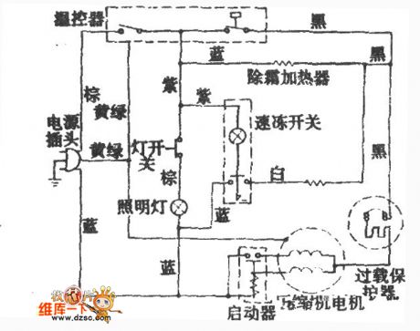
snowflake BCD-205 fridge circuit diagram
Published:2011/5/4 7:57:00 Author: | Keyword: fridge, circuit
View full Circuit Diagram | Comments | Reading(499)
Passive driver amplifier circuit
Published:2011/5/3 18:56:00 Author:Christina | Keyword: Passive driver, amplifier
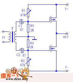
The author made a heterogeneous amplifier which is composed of the old radio's output transformer and two FETs, use this amplifier with the AL007 sound card, the effect is good. This is one kind of simple amplifier and it is suitable for the beginners to copy. The circuit is as shown. Signal from the sound card gets into the transformer T primary stage (the original radio's output transformer is used as the input transformer, the original secondary stage transformer is used as the primary stage transformer), this signal is boosted by the transformer and gets into the FET through capacitors C1 and C2, the FET enlarges this signal to drive the speaker. The trick of this circuit is: uses the passive components voltage amplifier stage. For the low input impedance, this device can be only used to continue the low output impedance's signal. Power supply can work in ±6V~±24V voltage condition and you just need to adjust R1, R2 to keep the 30mA quiescent current.
(View)
View full Circuit Diagram | Comments | Reading(723)
USB Multimedia 2.5W+2.5W Circuit
Published:2011/5/3 6:59:00 Author:Felicity | Keyword: USB Multimedia 2.5W+2.5W Circuit,

The picture above shows the USB Multimedia 2.5W+2.5W Circuit. (View)
View full Circuit Diagram | Comments | Reading(476)
Hitachi TV-used Movement NP84C Circuit
Published:2011/5/3 6:39:00 Author:Felicity | Keyword: Hitachi TV-used Movement Circuit,

The picture shows the Hitachi TV-used Movement NP84C Circuit. (View)
View full Circuit Diagram | Comments | Reading(1042)
snowflake BYD170A fridge circuit diagram
Published:2011/5/3 8:19:00 Author: | Keyword: BYD170A, fridge, circuit
View full Circuit Diagram | Comments | Reading(481)
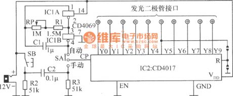
oscillator circuit and trigger circuit diagram
Published:2011/5/3 8:13:00 Author: | Keyword: oscillator circuit, trigger circuit
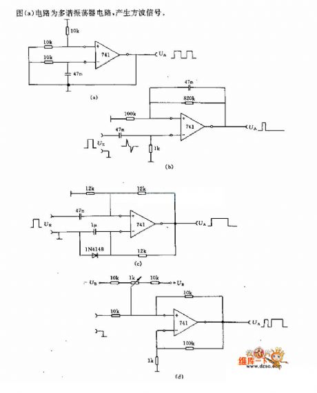
Diagram (a) circuit is a multivibrator type oscillator circuit, generating Square-Wave signal.
(View)
View full Circuit Diagram | Comments | Reading(418)
single-port A-type amplifier circuit
Published:2011/5/3 9:56:00 Author:Christina | Keyword: single-port, A-type
View full Circuit Diagram | Comments | Reading(509)
Changqing BYD-230 fridge circuit
Published:2011/5/3 7:20:00 Author:Christina | Keyword: Changqing, fridge
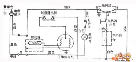
The Changqing BYD-230 fridge circuit is as shown:
(View)
View full Circuit Diagram | Comments | Reading(446)
Electronic pulse tester circuit
Published:2011/5/3 6:55:00 Author:Christina | Keyword: Electronic pulse, tester
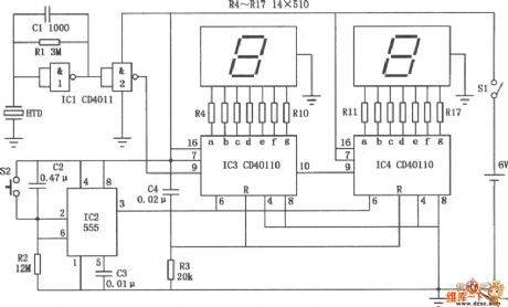
The Electronic pulse tester circuit is as shown:
(View)
View full Circuit Diagram | Comments | Reading(1000)
Taiwan dual independent refrigeration system fridge circuit
Published:2011/5/3 6:42:00 Author:Christina | Keyword: Taiwan, dual independent, refrigeration system

The Taiwan dual independent refrigeration system fridge circuit is as shown:
(View)
View full Circuit Diagram | Comments | Reading(1380)
Inverter drive signal generator circuit diagram
Published:2011/5/2 22:48:00 Author:Ecco | Keyword: Inverter , drive s, ignal generator
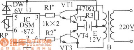
In the circuit shown as the chart, V1 ~ V4 are two composite switch amplifier tubes, of which V2 and V4 can be made by a few high-power tubes in parallel according to the power requirements of the inverter. B is the step-up transformer. Adjusting the resistance of RP could make the pin 3,4 IC output high and low frequency with 50Hz alternately. When the pin 3 outputs high level, VT1, VT2 are in saturation, VT3, VT4 end, when the pin 4 outputs high level, VT3, VT4 are in saturation, VT1, VT2 are closed. So the transformer generates electricity in two windings of the primary coil, the secondary coil can sense 220V, 50Hz square-wave voltage. (View)
View full Circuit Diagram | Comments | Reading(813)
Pulse dial display circuit diagram
Published:2011/5/2 21:28:00 Author:Rebekka | Keyword: Pulse dial, display circuit
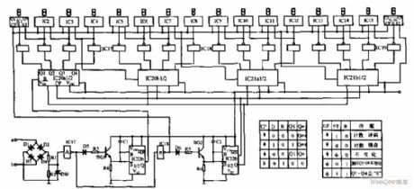
Pulse dial display circuit is shown as below, the circuit is mainly composed of the pulse count (IC1 ~ IC16), differential pulse string (IC22b), shift control (IC20, IC21), 16-bit digital displays and other components. The logic waveforms, timing waveforms are shown as the relevant information. (View)
View full Circuit Diagram | Comments | Reading(803)
| Pages:183/195 At 20181182183184185186187188189190191192193194195 |
Circuit Categories
power supply circuit
Amplifier Circuit
Basic Circuit
LED and Light Circuit
Sensor Circuit
Signal Processing
Electrical Equipment Circuit
Control Circuit
Remote Control Circuit
A/D-D/A Converter Circuit
Audio Circuit
Measuring and Test Circuit
Communication Circuit
Computer-Related Circuit
555 Circuit
Automotive Circuit
Repairing Circuit

