Index 194
1MHz oscillator circuit
Published:2011/3/21 0:57:00 Author:may | Keyword: oscillator, 1MHz

Use IC 7400 can make up a high frequency oscillator, its oscillator frequency depended on RC, the final 7400use for isolation level.
(View)
View full Circuit Diagram | Comments | Reading(1889)
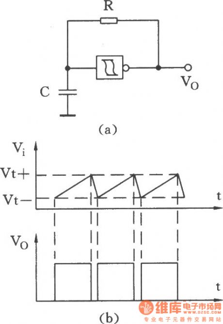
Oscillator circuit composed of Schmitt trigger with a resistor and a capacitor
Published:2011/4/6 20:06:00 Author:Ecco | Keyword: Oscillator circuit , Schmitt trigger , resistor , capacitor
View full Circuit Diagram | Comments | Reading(583)
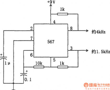
The twice frequency oscillator(567)
Published:2011/4/6 2:40:00 Author:Ecco | Keyword: twice frequency oscillator
View full Circuit Diagram | Comments | Reading(604)
Zero pulse circuit
Published:2011/4/6 21:43:00 Author:Ecco | Keyword: Zero pulse
View full Circuit Diagram | Comments | Reading(538)
Quantitative pulse generator
Published:2011/4/2 0:58:00 Author:Ecco | Keyword: Quantitative pulse , generator

This circuit is mainly used for the stepper motor rotation control. The number of input pulses determines the stepper motor rotation, the circuit can set up the quantity of pulses arbitrarily, and the maximum number is 999. (View)
View full Circuit Diagram | Comments | Reading(696)
100kHz sine wave oscillator circuit
Published:2011/3/27 22:41:00 Author:may | Keyword: sine wave oscillator
View full Circuit Diagram | Comments | Reading(820)
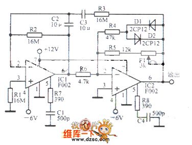
0.001Hz sinusoidal oscillator diagram
Published:2011/3/27 22:22:00 Author:may | Keyword: sinusoidal oscillator diagram
View full Circuit Diagram | Comments | Reading(945)
1-50KHz sinusoidal oscillator circuit diagram
Published:2011/3/25 1:12:00 Author:may | Keyword: 1-50KHz sinusoidal oscillator

1-50KHz sinusoidal oscillator circuit diagram is shown in the diagram:
(View)
View full Circuit Diagram | Comments | Reading(982)
2.34KHz sinusoidal oscillator circuit diagram
Published:2011/3/25 1:09:00 Author:may | Keyword: 2.34KHz sinusoidal oscillator
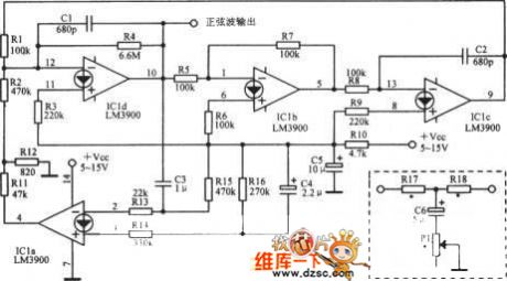
2.34KHz sinusoidal oscillator circuit diagram is shown in the diagram:
(View)
View full Circuit Diagram | Comments | Reading(460)
25Hz sinusoidal oscillator circuit diagram
Published:2011/3/25 1:09:00 Author:may | Keyword: 25Hz sinusoidal oscillator

25Hz sinusoidal oscillator circuit diagram is shown in the diagram:
(View)
View full Circuit Diagram | Comments | Reading(931)
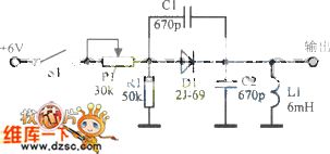
Negative oxygen | ion | generator circuit
Published:2011/3/27 21:43:00 Author:may | Keyword: Negative oxygen generator, ion generator

Negative oxygen | ion | generator circuit is shown in the diagram:
(View)
View full Circuit Diagram | Comments | Reading(693)
Practical pulse signal generator
Published:2011/3/31 3:36:00 Author:Ecco | Keyword: Practical, pulse signal , generator

Practical pulse signal generator is adjustable and shown in the chart.
The pulse frequency generation circuit is composed of Al and surrounding components, it connects to three different capacitances which corresponding to three frequency ranges respectively. RPl is used as fine-tuning the frequency. A3 and surrounding components compose of signal modulation circuit, and it divides in three block range, RP2 is used as fine-tuning the signal modulation frequency. RP3 is for the gain modulation of modulating signal. RP4 controls duty ratio. (View)
View full Circuit Diagram | Comments | Reading(836)
Ultra-low frequency pulse generator
Published:2011/3/31 3:27:00 Author:Ecco | Keyword: Ultra-low frequency , pulse generator

Ultra-low frequency pulse generator is shown in the chart. It could produce the pulse in the width range of 0.15~50s. (View)
View full Circuit Diagram | Comments | Reading(967)
Double pulse generator(HEF4538)
Published:2011/3/31 4:03:00 Author:Ecco | Keyword: Double pulse , generator
View full Circuit Diagram | Comments | Reading(3033)
1/86400Hz Pulse generator
Published:2011/3/31 4:02:00 Author:Ecco | Keyword: Pulse generator

The circuit shown in the chart coule be input 1Hz clock pulses, and it outputs a pulse every 24 hour. The input IHz pulse is produced by digital clock. It can provide the instructions of morning and afternoon that general digital clocks couldn't do. It also could be used as a pre-date electronic calendar and a reliable alarm trigger in particular time . (View)
View full Circuit Diagram | Comments | Reading(673)
Pulse signal generator(74LS10 74LS00)
Published:2011/3/31 3:38:00 Author:Ecco | Keyword: Pulse signal , generator
View full Circuit Diagram | Comments | Reading(1972)
74 series digital circuit of 74121 74L121 monostable multivibrator
Published:2011/3/30 2:39:00 Author:Ecco | Keyword: digital circuit, monostable multivibrator


To improve the precision and repeatability of the pulse width, it could connect a resistance between REXT/CEXT and VCC, and open for RINT.
To improve pulse width, it could connect atiming resistance betweenREXT/CEXT and CEXT. (View)
View full Circuit Diagram | Comments | Reading(1329)
74 series digital circuit of 74122 74L122 monostable multivibrator
Published:2011/3/30 2:43:00 Author:Ecco | Keyword: digital circuit, monostable multivibrator

To improve the precision and repeatability of the pulse width, it could connect a resistance between REXT/CEXT and VCC, and open for RINT. In order to get the variable pulse width, it could connect a variable resistance between RINT and VCC. (View)
View full Circuit Diagram | Comments | Reading(1319)
74 series digital circuit of 74123 74L123 double monostable multivibrator
Published:2011/3/30 1:42:00 Author:Ecco | Keyword: digital circuit, double monostable multivibrator


Capacitance. To improve the precision and repeatability of the pulse width, it could connect a resistance between REXT/CEXT and VCC, and open for RINT. In order to get the variable pulse width, it could connect a variable resistance between RINT and VCC.
74123, 74L123, 74LS123, 74HC123 double monostable multivibrator (View)
View full Circuit Diagram | Comments | Reading(762)
74 series digital circuit of 74LS124 74S124 double voltage controlled oscillator
Published:2011/3/29 22:38:00 Author:Ecco | Keyword: digital circuit , double voltage controlled oscillator
View full Circuit Diagram | Comments | Reading(2033)
| Pages:194/195 At 20181182183184185186187188189190191192193194195 |
Circuit Categories
power supply circuit
Amplifier Circuit
Basic Circuit
LED and Light Circuit
Sensor Circuit
Signal Processing
Electrical Equipment Circuit
Control Circuit
Remote Control Circuit
A/D-D/A Converter Circuit
Audio Circuit
Measuring and Test Circuit
Communication Circuit
Computer-Related Circuit
555 Circuit
Automotive Circuit
Repairing Circuit
