Index 191
The separate excitation crossover multivibrator
Published:2011/4/14 2:39:00 Author:Ecco | Keyword: separate excitation, crossover, multivibrator

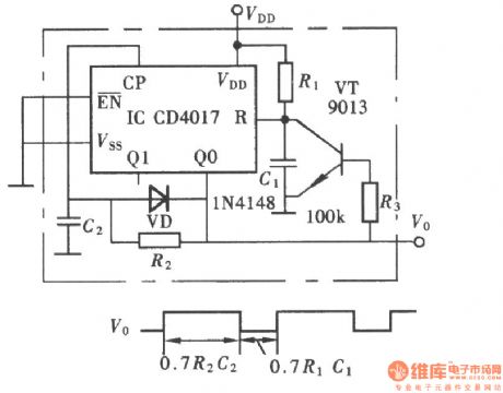
The separate excitation crossover multivibrator is shown in the chart. It has two or four types of split-phase output waveform, and can easily obtain 0°,-90°,-180°, 270°split-phase square wave. It has the features of simple structure, good output waveform, eliminating the traditional frequency, counting, decoding circuit. It should be used in the phase generator, four-cycle water lantern controller circuit,etc.
(View)
View full Circuit Diagram | Comments | Reading(611)
The separate excitation crossover oscillator used in four recirculating water lantern controller
Published:2011/4/14 2:40:00 Author:Ecco | Keyword: separate excitation rossover oscillator, four recirculating , water lantern , controller
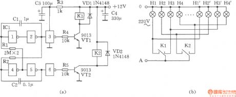
The figure shows the separate excitation crossover oscillator used in four recirculating water lantern controller, the circuit only adopts two sets of contactrelay 4088 to control the four water lanterns. The working principle: the six NOT gate CD4069 in ICl and C1, C2, Rl, R2 form the separate excitation crossover oscillator circuit, it controls the transistor VTl, VT2 directly and drives relays Kl, K2 for the cross-phase output, that is the after Kl pulls, then K2 pulls, and Kl disconnects, K2 then disconnects and go in the cycle. (B) shows the lantern connection diagram.
(View)
View full Circuit Diagram | Comments | Reading(536)
The stable function generator
Published:2011/4/14 2:32:00 Author:Ecco | Keyword: stable, function generator
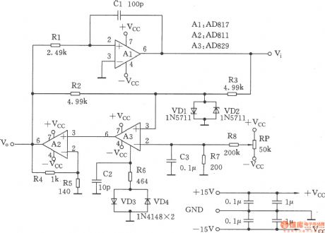
This circuit is a function generator, as shown. Its square-wave output has a short rise time and the amplitude is not sensitive to temperature; In addition,thetriangular output waveform changesat the exactlysame rate in the whole range.
(View)
View full Circuit Diagram | Comments | Reading(744)
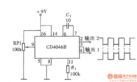
The opposite phase symmetric square wave produced by CD4046
Published:2011/4/14 2:31:00 Author:Ecco | Keyword: opposite phase , symmetric , square wave
View full Circuit Diagram | Comments | Reading(1633)
NC monostable multivibrator circuit
Published:2011/4/14 2:40:00 Author:Ecco | Keyword: NC, monostable , multivibrator

The NC monostable multivibrator circuit shown in the chart is composed of four 2 input NOR gate CC4001 and 14-bit binary serial counter / divider CC4020. It mainly used as time delay switch or timer in automatic control equipments. (View)
View full Circuit Diagram | Comments | Reading(1728)
Homemade gunfire analog generator
Published:2011/4/14 2:45:00 Author:Ecco | Keyword: Homemade gunfire , analog generator

Two transistors form a complementary audio oscillator which could be used as gunfire analog sound generator, and the sounds are realistic, rich in reverberation. The circuit is as shown. Selection of components: transistor VTl, VT2: 9014, β = 85 ~ 115, VT3, VT4: 9015, β = 65 ~ 85. Sl: AN4, S2: KN3. LED VDl ~ VD6: BT201, can also choose other models, the best selection is the LED in low power, high luminous efficiency. Battery GB: 4F22DC6V stacked batteries. Speaker BL: 8Ω, 0.25W.
(View)
View full Circuit Diagram | Comments | Reading(1377)
Rain generator composed of NE555
Published:2011/4/14 2:45:00 Author:Ecco | Keyword: Rain generator

This circuit is very simple, it's composed of regular component, which includes two oscillators, one is a frequency oscillator of single-junction transistors VTl (2N2646) variable, VTl can oscillate without resonant coils, the circuit is shown in the chart.
(View)
View full Circuit Diagram | Comments | Reading(2032)
Simple seashore generator
Published:2011/4/14 2:46:00 Author:Ecco | Keyword: Simple, seashore generator
View full Circuit Diagram | Comments | Reading(831)
Variable duty cycle monostable multivibrator composed of 74HCT221
Published:2011/4/13 3:17:00 Author:Ecco | Keyword: Variable duty cycle, monostable multivibrator
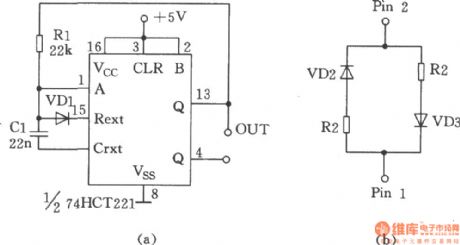
The chart shows the variable duty cycle monostable multivibrator composed of 74HCT221. Capacitor C is charged and discharged at the same rate, the duty cycle is 50%, the oscillation period T = RC. The R in figure (a) can be replaced by the map to get other desired duty cycle, during this time, Cl is charged by R1, and discharged by R2, the oscillation period T = (R1 + R2) C / 2, the duty cycle is approximately Rl / (R1 + R2). In the figure 9-11, VDl, VD2, VD3 is the 1N4148. (View)
View full Circuit Diagram | Comments | Reading(1151)
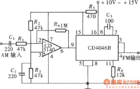
The frequency-modulated signal generator composed of CD4046
Published:2011/4/13 4:27:00 Author:Ecco | Keyword: frequency-modulated signal, generator
View full Circuit Diagram | Comments | Reading(1468)
1Hz Clock signal source circuit(CD4060、CD4027)
Published:2011/4/13 4:25:00 Author:Ecco | Keyword: 1Hz , Clock signal source
View full Circuit Diagram | Comments | Reading(5492)
Fancy lantern circuit diagram
Published:2011/4/12 21:33:00 Author:Rebekka | Keyword: fancy lantern
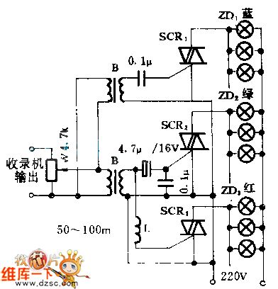
The circuit is 3-way fancy lantern circuit. It uses frequency division effect to divide the trigger triac audio signals into 3 frequency, high, medium and low. They are used for triggering SCR1,SCR2,SCR33 controlled silicon to controll blue, green, red 3-way lights. The 3 colors lights changes with the music melody beautifully.
(View)
View full Circuit Diagram | Comments | Reading(580)
PLL pulse generator(74HC4060、TC9122P)
Published:2011/4/13 2:38:00 Author:Ecco | Keyword: PLL , pulse generator

The PLL pulse generator is shown as the chart. The circuit is the phase-locked loop (PLL) pulse generator circuit. PLL makes a fractional frequency to crystal oscillator and gets 1kHz stepped frequency signal, moreover, it obtains 10kHz 999kHz pulse waveform on the output terminal. The manifold block 74HC4060 is a type of integrated chip with NOT gate and 1/2n frequency dividing circuit inside, among them, the NOT gate and the crystal oscillator with 4.096MHz form a oscillator circuit, and the frequency dividing circuit gets lkHz reference frequency signal by it.TC9122P is a high-speed programmable counter and its dividing ratio is decided by the BCD code, the programming data make the frequency ratio range be in 8 to 999, the circuit operates under the dividing ratio between 10 and 999. There are 3 types of phase comparator in 74HC4060, and the phase comparator PC2 can compare the output frequency with the positive edge of reference frequency, and get their feedback. The oscillation frequency of VC0 is decided by Cx, R1 and R2.
(View)
View full Circuit Diagram | Comments | Reading(5582)
The multivibrator composed of CD4017
Published:2011/4/13 2:17:00 Author:Ecco | Keyword: multivibrator
View full Circuit Diagram | Comments | Reading(614)
The pulse generator with adjustable duty cycle and frequency
Published:2011/4/13 2:15:00 Author:Ecco | Keyword: pulse generator w, adjustable duty cycle , adjustable frequency
View full Circuit Diagram | Comments | Reading(3094)
Pulse width controllable pulse generator composed of CC4516
Published:2011/4/13 2:14:00 Author:Ecco | Keyword: Pulse width, controllable , pulse generator
View full Circuit Diagram | Comments | Reading(652)
Simple pulse signal generator composed of 74LS00、74LS221
Published:2011/4/13 2:12:00 Author:Ecco | Keyword: Simple , pulse signal generator

The simple pulse generator circuit is shown as the chart. The pulse generator mainly adopts two TTL signal generator IC (74LS00 and 74LS221) to generte the τ = 4μs pulse signal, it uses fewer components, so it's easy to do debugging and maintenance.
(View)
View full Circuit Diagram | Comments | Reading(2093)
LC square wave generator
Published:2011/4/13 1:50:00 Author:Ecco | Keyword: LC , square wave , generator

Square-wave generator with LC circuit can get a better frequency stability, it's as shown in the chart. This three-terminal oscillator of capacitor can be used to generate a square wave, but an operational amplifier is used as the active component.
(View)
View full Circuit Diagram | Comments | Reading(2373)
Duplex pulse generator composed of CD4013
Published:2011/4/12 22:58:00 Author:Ecco | Keyword: Duplex pulse generator

In the design of digital circuit, sometimes it requires a group of two-phase pulse signal. Figure shows the duplex pulse generator composed of CD4013. (A) is schematic; (b) the waveform chart.
(View)
View full Circuit Diagram | Comments | Reading(4349)
Rapid synchronous vco
Published:2011/4/12 22:52:00 Author:Ecco | Keyword: Rapid , synchronous, vco
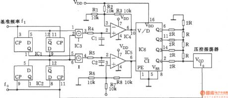
The main function of this circuit is to combine phase splitter and digital / analog converter, it can make the high stability VCO and the external reference frequency be precisely synchronized. (View)
View full Circuit Diagram | Comments | Reading(618)
| Pages:191/195 At 20181182183184185186187188189190191192193194195 |
Circuit Categories
power supply circuit
Amplifier Circuit
Basic Circuit
LED and Light Circuit
Sensor Circuit
Signal Processing
Electrical Equipment Circuit
Control Circuit
Remote Control Circuit
A/D-D/A Converter Circuit
Audio Circuit
Measuring and Test Circuit
Communication Circuit
Computer-Related Circuit
555 Circuit
Automotive Circuit
Repairing Circuit
