Signal Processing
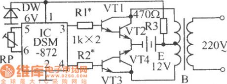
Inverter drive signal generator circuit diagram
Published:2011/5/2 22:48:00 Author:Ecco | Keyword: Inverter , drive s, ignal generator | From:SeekIC

In the circuit shown as the chart, V1 ~ V4 are two composite switch amplifier tubes, of which V2 and V4 can be made by a few high-power tubes in parallel according to the power requirements of the inverter. B is the step-up transformer. Adjusting the resistance of RP could make the pin 3,4 IC output high and low frequency with 50Hz alternately. When the pin 3 outputs high level, VT1, VT2 are in saturation, VT3, VT4 end, when the pin 4 outputs high level, VT3, VT4 are in saturation, VT1, VT2 are closed. So the transformer generates electricity in two windings of the primary coil, the secondary coil can sense 220V, 50Hz square-wave voltage.
Reprinted Url Of This Article:
http://www.seekic.com/circuit_diagram/Signal_Processing/Inverter_drive_signal_generator_circuit_diagram.html
Print this Page | Comments | Reading(3)

Article Categories
power supply circuit
Amplifier Circuit
Basic Circuit
LED and Light Circuit
Sensor Circuit
Signal Processing
Electrical Equipment Circuit
Control Circuit
Remote Control Circuit
A/D-D/A Converter Circuit
Audio Circuit
Measuring and Test Circuit
Communication Circuit
Computer-Related Circuit
555 Circuit
Automotive Circuit
Repairing Circuit
Code: