
Index 136
VIDEO_LINE_RECEIVER
Published:2009/6/24 4:28:00 Author:Jessie

This circuit can achieve 46-dB common-mode rejection if R1, R2, R3, and R4 are matched to 1%. C1 is adjusted for best CMR above 1 MHz. (View)
View full Circuit Diagram | Comments | Reading(603)
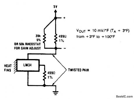
THERMOCOUPLE_COLD_JUNCTION_COMPENSATION
Published:2009/6/24 4:27:00 Author:Jessie

A single-supply circuit is shown. R3 and R4 divide down the 10-mV/°K output of the LM329B and its associated voltage divider provide a voltage to buck out the 0℃ output of the LM335. To calibrate, adjust R1 so that V1 = αT, where cc is the Seebeck coefficient and T is the ambient temperature in degrees Kelvin. Then, adjust R2 so that V1 - V2 is equal to the thermocouple output voltage at the known ambient temperature. (View)
View full Circuit Diagram | Comments | Reading(1102)
SIMPLE_CRYSTAL_RADIO
Published:2009/6/24 4:27:00 Author:Jessie
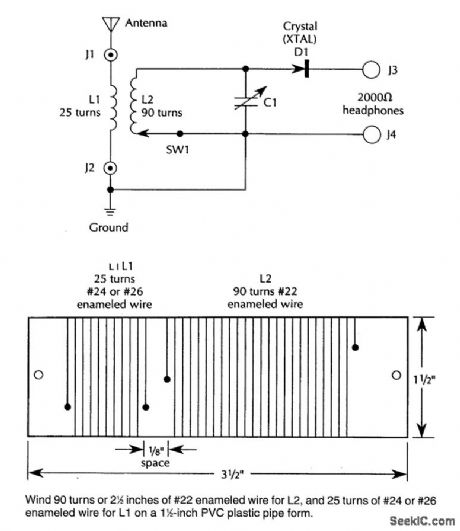
An IN34A (D1) is used as a detector in this crystal radio. A good outdoor antenna should be used. (View)
View full Circuit Diagram | Comments | Reading(2843)
TWO_BAND_RADIO
Published:2009/6/24 4:25:00 Author:Jessie
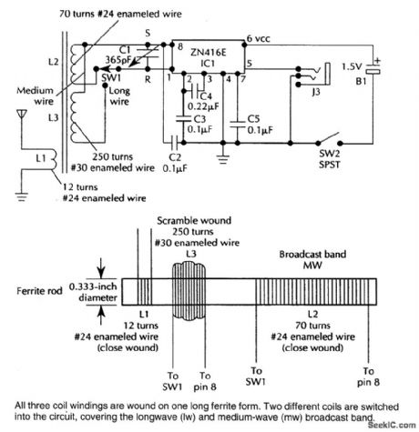
This TRF receiver covers the AM broadcast band and longwave bands (used in Europe and Asia for broadcasting). A loop antenna is used for reception and an extemal antenna can be connected.Frequency coverage is 150 to 1600 kHz. (View)
View full Circuit Diagram | Comments | Reading(3815)
ONE_TUBE_REGENERATIVE_AM_RECEIVER
Published:2009/6/24 4:24:00 Author:Jessie
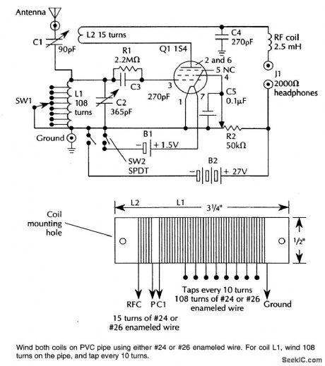
Suitable for AM reception and as a simple radio project, this circuit uses a single tube as a regenerative detector. (View)
View full Circuit Diagram | Comments | Reading(3711)
AF_POWER_OSCILLATOR
Published:2009/6/24 4:15:00 Author:May

An LM386 audio power IC is set up as a feedback oscillator. Any supply from 6 to 12 V can be used. The circuit can drive a loudspeaker. (View)
View full Circuit Diagram | Comments | Reading(0)
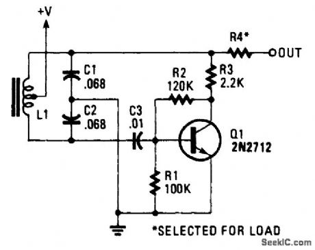
SIMPLE_RF_TEST_OSCILLATOR
Published:2009/6/24 4:13:00 Author:May

A simple oscillator for IF alignment (455 kHz) can prove useful in field testing or where a stan-dard signal generator is available. L1 should res-onate at the desired output frequency with the series combination of C2 and C3. (View)
View full Circuit Diagram | Comments | Reading(1358)
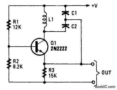
MOSFET_MXER_OSCILLATOR_CIRCUIT_FOR_AM_RECEIVERS
Published:2009/6/24 4:10:00 Author:May
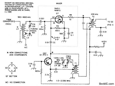
This circuit is an improved front end for upgrading a transistor AM receiver. This front end is useful when the radio is to be used as a tuneable IF amplifier with shortwave converters. (View)
View full Circuit Diagram | Comments | Reading(1776)
COLPITTS_OSCILLATOR
Published:2009/6/24 4:07:00 Author:May
View full Circuit Diagram | Comments | Reading(0)
LC_AUDIO_OSCILLATOR
Published:2009/6/24 4:06:00 Author:May
View full Circuit Diagram | Comments | Reading(0)
NE602_LOCAL_OSCILLATOR_CIRCUITS
Published:2009/6/24 4:05:00 Author:May
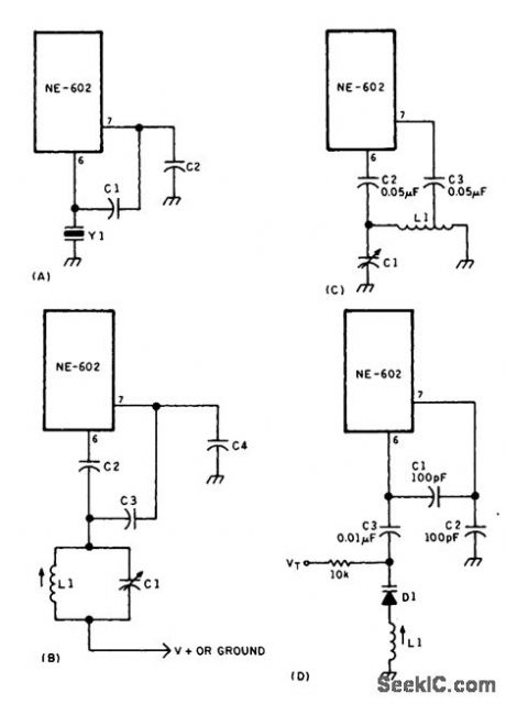
Local oscillator circuits for the NE602. (View)
View full Circuit Diagram | Comments | Reading(0)
TWO_WIER_REMOTE_TEMPERATURE_SENSOR_WITH_SENSOR_GROUNDED
Published:2009/6/24 4:13:00 Author:Jessie
View full Circuit Diagram | Comments | Reading(578)
EIGHT_INPUT_A_D_CONVERTER_FOR_TEMPERATURE_MEASUREMENTS
Published:2009/6/24 4:03:00 Author:Jessie


The actual processing circuitry of this A/D converter consists of only four parts: U2, U3, R1 and R2. Eight temperature probes are used with the circuit; however, they can be replaced with other types of sensors, as long as resistors R3 through R10 are removed.
(View)
View full Circuit Diagram | Comments | Reading(4013)
AM_FM_RECEIVER_CIRCUIT
Published:2009/6/24 3:48:00 Author:Jessie
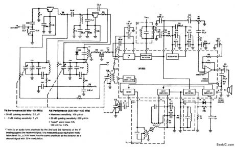
This circuit shows the LM1868 as a complete AM radio and FM IF section. An extemal FM front end is used for the 88- to 108-MHz band. Audio output is 0.5 W and either 9-V battery or line operated supply can be used. (View)
View full Circuit Diagram | Comments | Reading(1675)
SHORTWAVE_RECEIVER
Published:2009/6/24 3:45:00 Author:Jessie
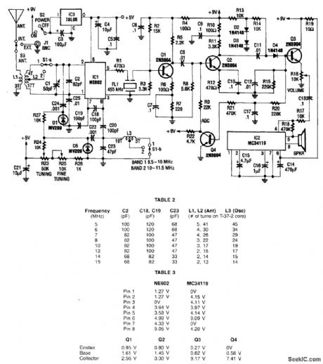
This receiver covers 8.5 to 11.5 MHz in two bands and has a sensitivity of under 1 μV. Nn NE602 mixer feeds a 455-kHz IF amplifier (Q1 and Q2), detector D4, and audio amplifier IC2. Q4 serves as an AGC amplifier coil data is given in the table. The LO is varactor tuned. (View)
View full Circuit Diagram | Comments | Reading(3368)
ac/dc_VACUUM_TUBE_AM_AND_SHORTWAVE_RECEIVER
Published:2009/6/24 3:38:00 Author:Jessie


This circuit was used in a World War II vintage AM/SW(6 to 18 MHz)recelver and shows typical circuits used in recelvers at that time. (View)
View full Circuit Diagram | Comments | Reading(1540)
26_GHz_OSCILLATOR_FOR_RADAR_SPEED_GUN
Published:2009/6/24 3:19:00 Author:May
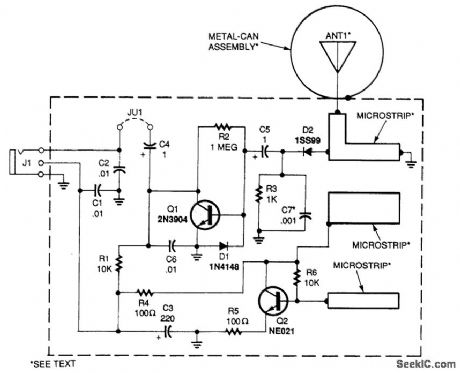
This circuit consists of 2.6-GHz oscillator Q2, a coupling rrticrostripline to ANT1, a 1.1 1/4 wave probe, detector D2, and audio amp Q1. The oscillator feeds power to the antenna, which radiates the signal. The reflected signal from a moving target mixes with the oscillator signal in D2. The resultant beat note (doppler shift) is amplified by Q1 and fed to jack J1, which is used to feed the circuit 12 Vdc. (View)
View full Circuit Diagram | Comments | Reading(2146)
STEPPER_MOTOR_PULSE_GENERATOR
Published:2009/6/24 2:59:00 Author:May
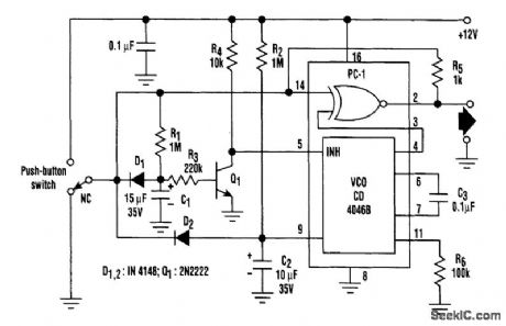
When the switch is in its normally closed (NC) position, capacitors C1 and C2 are held discharged by diodes Dl and D2. Switching off transistor Q1 inhibits the voltage-controlled oscillator of the PLL. The two inputs and, hence, the output of the EX-OR gate (phase comparator 1) ofthe PLL remain at the logic 0 level.When the pushbutton is pressed, C1 and C2 are allowed to charge via resistors R1 and R2. The VCO is enabled only after a time delay (≈0.5 second) set by R1, R3, and C1. During this delay period, the EX-OR gate output follows the logic level at the switch output. As a result, one-shot pulses can be generated by pressing the pushbutton, then releasing it within 0.5 second. R5 provides the switch-debouncing function.If the pushbutton is pressed for more than 0.5 second, the VCO is enabled. The rising voltage at the control input (pin 9) causes a linear increase in VCO frequency and thus accelerates the step-per motor. Releasing the pushbutton discharges C1 and C2 and inhibits the VCO. (View)
View full Circuit Diagram | Comments | Reading(1620)
UP_DOWN_STAIRCASE_WAVE_GENERATOR
Published:2009/6/24 2:56:00 Author:May

This staircase waveform first steps up and then steps down by the circuit shown. An input pulse generator provides the pulses that cause the output to step up or down, depending on the conduc-tion of the clamp transistor, Q1. When this is ON, the down current pulse is diverted to ground and the staircase then steps up. When the upper voltage trip point of Amp 2 is reached, Q1 goes OFF and as a result of the smaller down input resistor (one-half the value of the up resistor, R1), the staircase steps down to the low-voltage trip point of Amp 2. The output voltage, therefore, steps up and down between the trip voltages of the Schmitt Trigger. (View)
View full Circuit Diagram | Comments | Reading(2262)
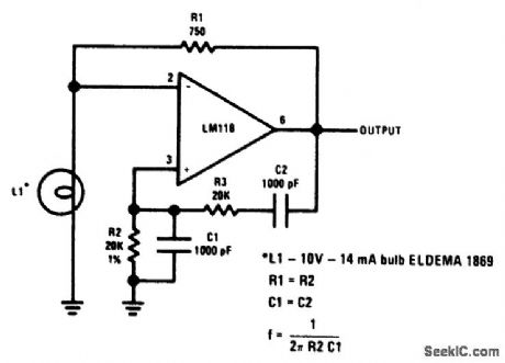
WIEN_BRIDGE_SINE_WAVE_OSCILLATOR_1
Published:2009/6/24 2:56:00 Author:May
View full Circuit Diagram | Comments | Reading(703)
| Pages:136/195 At 20121122123124125126127128129130131132133134135136137138139140Under 20 |
Circuit Categories
power supply circuit
Amplifier Circuit
Basic Circuit
LED and Light Circuit
Sensor Circuit
Signal Processing
Electrical Equipment Circuit
Control Circuit
Remote Control Circuit
A/D-D/A Converter Circuit
Audio Circuit
Measuring and Test Circuit
Communication Circuit
Computer-Related Circuit
555 Circuit
Automotive Circuit
Repairing Circuit