Signal Processing
STEPPER_MOTOR_PULSE_GENERATOR
Published:2009/6/24 2:59:00 Author:May | From:SeekIC

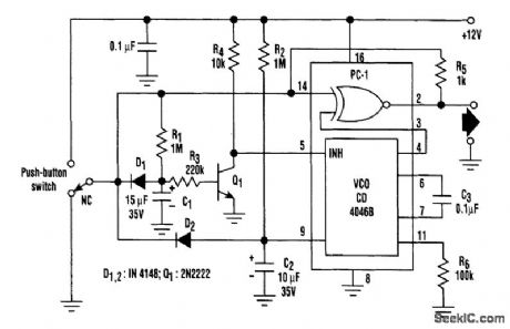
When the switch is in its normally closed (NC) position, capacitors C1 and C2 are held discharged by diodes Dl and D2. Switching off transistor Q1 inhibits the voltage-controlled oscillator of the PLL. The two inputs and, hence, the output of the EX-OR gate (phase comparator 1) ofthe PLL remain at the logic 0 level.When the pushbutton is pressed, C1 and C2 are allowed to charge via resistors R1 and R2. The VCO is enabled only after a time delay (≈0.5 second) set by R1, R3, and C1. During this delay period, the EX-OR gate output follows the logic level at the switch output. As a result, one-shot pulses can be generated by pressing the pushbutton, then releasing it within 0.5 second. R5 provides the switch-debouncing function.If the pushbutton is pressed for more than 0.5 second, the VCO is enabled. The rising voltage at the control input (pin 9) causes a linear increase in VCO frequency and thus accelerates the step-per motor. Releasing the pushbutton discharges C1 and C2 and inhibits the VCO.
Reprinted Url Of This Article:
http://www.seekic.com/circuit_diagram/Signal_Processing/STEPPER_MOTOR_PULSE_GENERATOR.html
Print this Page | Comments | Reading(3)

Article Categories
power supply circuit
Amplifier Circuit
Basic Circuit
LED and Light Circuit
Sensor Circuit
Signal Processing
Electrical Equipment Circuit
Control Circuit
Remote Control Circuit
A/D-D/A Converter Circuit
Audio Circuit
Measuring and Test Circuit
Communication Circuit
Computer-Related Circuit
555 Circuit
Automotive Circuit
Repairing Circuit
Code: