power supply circuit
Index 258
24V CRT high voltage power supply circuit diagram
Published:2011/4/14 2:42:00 Author:Ecco | Keyword: 24V, CRT, high voltage, power supply

Some cameras use 11.4cm (4.5 inches) pure flat CRT as the display component, the anode voltage of high-voltage components is +20 kV, focus electrode voltage is +3.2 kV, accelerating voltage is +1000 V, the power supply of high voltage components is DC in 24V. It's as the chart shown:
Basic principles: NE555 constitutes pulse generator, to adjust potentiometer VR2 can generate a pulse with the frequency in about 20kHz, potentiometer VR1 adjusts the pulse width. TR1 is driver stage, the pulse transformer T1 adopts reverse polarity excitation, that is TR1 being on while TR2 being off, TR2 being on while TR1 being off, D3, C9, VR3, R7 and D4, R6, TR3 form a high-voltage protection circuit. VR2 is used for adjusting the frequency, and VR2 is used for adjusting the size of high voltage.
VR2 uses precision adjustable resistors. T2 can adopt colour TV line output transformer. The writer uses the Toyo SE-1438G Series of 35cm (14 inch) color TV line output transformer, with the anode voltage up to 20kV, and then choose the resistance of R8 to make acceleration voltage be +1000 V, the resistance of R9 make the focus electrode voltage be +3.2 kV. The whole part is packaged with aluminum box, aluminum jacket is connected to the earth to reduce the interference on the circuit.
(View)
View full Circuit Diagram | Comments | Reading(4983)
Using large capacitor C to instead back up battery circuit
Published:2011/4/13 3:09:00 Author:Nicole | Keyword: large capacitor C, back up battery
View full Circuit Diagram | Comments | Reading(663)
PIC16C72 and X9241 interface circuit
Published:2011/4/13 3:47:00 Author:Nicole | Keyword: interface
View full Circuit Diagram | Comments | Reading(1018)
MAXl898 single node Li + battery linear charger
Published:2011/4/13 3:57:00 Author:Nicole | Keyword: single node Li, battery linear charger
View full Circuit Diagram | Comments | Reading(538)
MAX846A most typical application circuit charging circuit
Published:2011/4/13 4:01:00 Author:Nicole | Keyword: charging

In figure, MAX846A is as a free limit voltage current source to charge to lithium ion battery.
(View)
View full Circuit Diagram | Comments | Reading(593)
DUM23-48/300Ⅱ DC distribution unit electrical schematic diagram
Published:2011/3/23 1:38:00 Author:muriel | Keyword: DUM23-48/300Ⅱ, DC distribution unit , electrical schematic diagram

As shown in the figure:B2(13) and B3(14) are hall current sensors; FU9(9) and FU10(10) are fuses; AP646 is fusing alarm signal board;X24、X26 and X29 are terminals of the user interface board; XT is socket. (View)
View full Circuit Diagram | Comments | Reading(915)
BQ2057 package
Published:2011/4/2 2:12:00 Author:may | Keyword: package

BQ2057 is advanced lithium ion battery charging IC. It is produced by America TI company. It can satisfy the charging need of simple link (4.1V or 4.2V) or two link (8.2V or 8.4V) lithium ion battery and polymer lithium ion battery. Meanwhile it offerd package choose of MSOP, TSSOP and SOIC, etc according to different application. The charger peripheral circuit designed by BQ2057 is simple. It is well suited to compact design need of portable type electronic product.
(View)
View full Circuit Diagram | Comments | Reading(701)
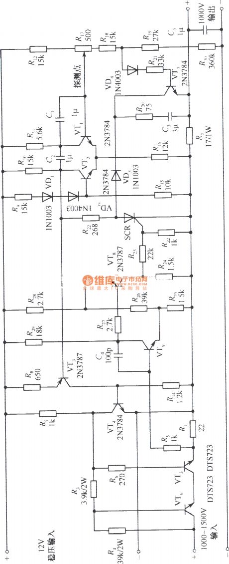
1000V High-pressure output DC regulated voltage power supply circuit
Published:2011/3/22 22:52:00 Author:muriel | Keyword: 1000V, High-pressure output, DC , regulated voltage power supply circuit
View full Circuit Diagram | Comments | Reading(1279)
1000W Automatic voltage regulating AC regulated voltage power supply
Published:2011/3/22 22:51:00 Author:muriel | Keyword: 1000W , Automatic, voltage regulating , AC , regulated voltage power supply
View full Circuit Diagram | Comments | Reading(1125)
High input voltage integrated regulated voltage power supply circuit with CW200 No.1
Published:2011/3/30 2:19:00 Author:muriel | Keyword: High input voltage, integrated , regulated voltage power supply
View full Circuit Diagram | Comments | Reading(512)
High input voltage integrated regulated voltage power supply circuit with CW200 No.2
Published:2011/3/30 2:20:00 Author:muriel | Keyword: High input voltage, integrated , regulated voltage power supply
View full Circuit Diagram | Comments | Reading(494)
50V suspension regulated voltage power supply with CA723C
Published:2011/3/30 2:20:00 Author:muriel | Keyword: 50V , suspension, regulated voltage power supply
View full Circuit Diagram | Comments | Reading(600)
CATV amplifier power circuit
Published:2011/3/21 22:43:00 Author:muriel | Keyword: CATV amplifier, power circuit, UC2842AN

The IC is pulse width modulation regulated IC 2 pin is output voltage adjustable regulator feet3 pin is over-current protection feet4 pin is output voltage control feet6 pin is driver output feet7 pin is power and over-voltage protection feet8 pin is regulated control input feet (View)
View full Circuit Diagram | Comments | Reading(3316)
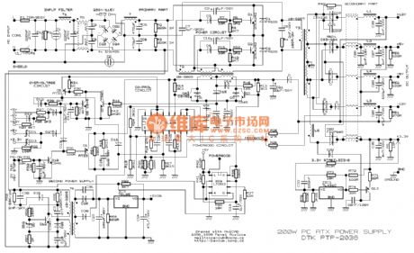
Atx power supply schematic diagram
Published:2011/3/22 0:44:00 Author:muriel | Keyword: Atx , power supply , schematic diagram
View full Circuit Diagram | Comments | Reading(3883)
6~18V Precision regulated voltage power supply circuit
Published:2011/3/22 22:58:00 Author:muriel | Keyword: 6~18V , regulated voltage power supply
View full Circuit Diagram | Comments | Reading(785)
6~30V、500mA Regulated voltage power supply circuit
Published:2011/3/22 22:58:00 Author:muriel | Keyword: 6~30V, 500mA, Regulated voltage power supply
View full Circuit Diagram | Comments | Reading(1230)
5V、1A Switch regulated voltage power supply
Published:2011/3/22 22:58:00 Author:muriel | Keyword: 5V, 1A, Switch, regulated voltage power supply
View full Circuit Diagram | Comments | Reading(750)
5V/1A AC adapter
Published:2011/3/21 0:44:00 Author:muriel | Keyword: 5V/1A, AC adapter
View full Circuit Diagram | Comments | Reading(1051)
5V、6A Switch regulated voltage power supply
Published:2011/3/22 22:58:00 Author:muriel | Keyword: 5V, 6A, Switch, regulated voltage power supply
View full Circuit Diagram | Comments | Reading(823)
5V、5A Switch regulated voltage power supply
Published:2011/3/22 22:58:00 Author:muriel | Keyword: 5V, 5A, Switch , regulated voltage power supply
View full Circuit Diagram | Comments | Reading(724)
| Pages:258/291 At 20241242243244245246247248249250251252253254255256257258259260Under 20 |
Circuit Categories
power supply circuit
Amplifier Circuit
Basic Circuit
LED and Light Circuit
Sensor Circuit
Signal Processing
Electrical Equipment Circuit
Control Circuit
Remote Control Circuit
A/D-D/A Converter Circuit
Audio Circuit
Measuring and Test Circuit
Communication Circuit
Computer-Related Circuit
555 Circuit
Automotive Circuit
Repairing Circuit


