
power supply circuit
Index 244
Multi-Control Four Switch Circuit
Published:2011/4/21 20:19:00 Author:Robert | Keyword: Multi-Control, Four Switch

Multi-ControlFour Switch Circuit is shown below:
(View)
View full Circuit Diagram | Comments | Reading(604)
INA103 Adjustable Offset Voltage Circuit
Published:2011/4/21 8:01:00 Author:Robert | Keyword: Adjustable Offset Voltage

INA103 Adjustable Offset Voltage Circuit is shown below:
(View)
View full Circuit Diagram | Comments | Reading(698)
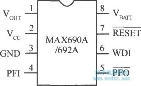
Microcomputer system power supply monitoring integrated chip MAX690A/692A
Published:2011/4/21 4:34:00 Author:Nicole | Keyword: Microcomputer system, integrated chip, power supply monitoring
View full Circuit Diagram | Comments | Reading(692)
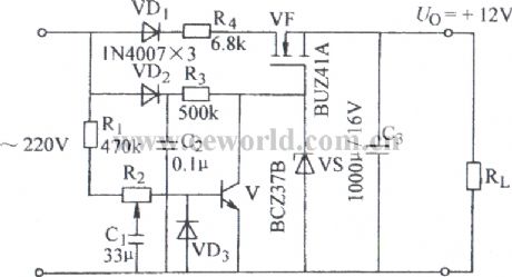
Circuit example of regulated power supply adding overvoltage protection
Published:2011/4/21 4:04:00 Author:Nicole | Keyword: regulated power supply, overvoltage protection

View full Circuit Diagram | Comments | Reading(480)
Regulated power supply circuit without transformer
Published:2011/4/21 4:27:00 Author:Nicole | Keyword: regulated power supply, transformer
View full Circuit Diagram | Comments | Reading(2140)
Walkman external power circuit without AC noise
Published:2011/4/21 4:28:00 Author:Nicole | Keyword: Walkman, external power, AC noise

View full Circuit Diagram | Comments | Reading(522)
Pocket switch power supply charger circuit
Published:2011/4/21 3:56:00 Author:Nicole | Keyword: switch power supply, charger
View full Circuit Diagram | Comments | Reading(630)
Common regulated power supply
Published:2011/4/21 4:37:00 Author:Nicole | Keyword: regulated power supply

View full Circuit Diagram | Comments | Reading(590)
Common mobile phone battery charger circuit BQ2057
Published:2011/4/21 4:39:00 Author:Nicole | Keyword: mobile phone battery, charger
View full Circuit Diagram | Comments | Reading(1485)
Common mobile phone battery charger circuit(BQ2057)
Published:2011/4/21 4:40:00 Author:Nicole | Keyword: mobile phone battery, charger
View full Circuit Diagram | Comments | Reading(1911)
The most simple and practical switching power supply circuit diagram
Published:2011/3/30 22:12:00 Author:Ecco | Keyword: most simple, most practical, switching

Simple switching supply circuit diagram with a triode:
(View)
View full Circuit Diagram | Comments | Reading(5646)
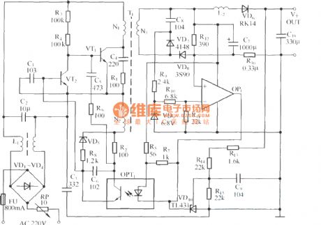
High and stabilized voltage circuit diagram with photocoupler
Published:2011/3/30 22:48:00 Author:Ecco | Keyword: photocoupler, High voltage , stabilized voltage
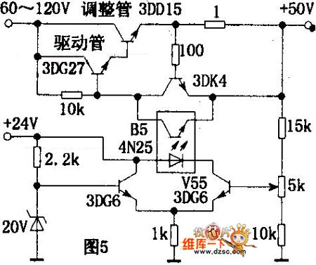
The circuitry is shown as chart. The drive tube need to adopt a transistor which can bear higher pressure(the drive tube is 3DG27). When output voltage enlarges, the bias of V55 raises, the forwarddirection current of the light-emitted diode in B5 will rise, and the voltage in the electrode of photosensitive tube minishes, the bias of regulator tube decreases while the internal resistance increses, then make the output voltage stable. (View)
View full Circuit Diagram | Comments | Reading(574)
Ni-Cd storage battery with 6v12v/2A automatical charging equipment
Published:2011/4/21 1:20:00 Author:Nicole | Keyword: Ni-Cd storage battery, charging equipment
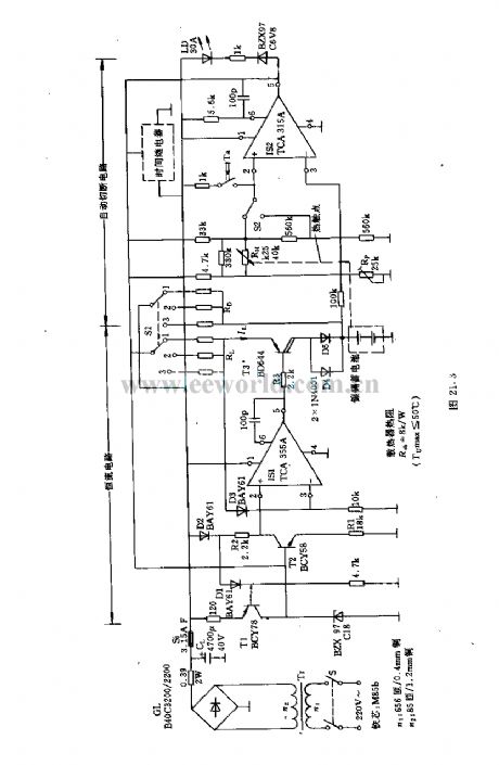
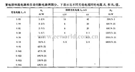
This automatical charging equipment can ensure the storage battery has a good process of charging, it also can prevent overload. It has three charging methods: standard charging, sustainable(microflow )charging and fast charging, they have differences in charging current and cuting the process of charging.
(View)
View full Circuit Diagram | Comments | Reading(588)
TOSHIBA AG series rear-projection TV supply circuit diagram
Published:2011/3/30 23:22:00 Author:Ecco | Keyword: rear-projection TV

TOSHIBA AG series rear-projection TV supply circuit diagram is as below:
(View)
View full Circuit Diagram | Comments | Reading(3630)
Photoelectricity logic circuit
Published:2011/4/13 9:18:00 Author:Nicole | Keyword: photoelectricity logic circuit

Q1, Q2 phototransistor is illuminated about 1076.4 lx(100feet one candle), Q3 output is zero. When a or two phototransistors is no illumination, Q3 output is positive or 1.
This circuit can be used as electro-optical logic exciter of power device. (View)
View full Circuit Diagram | Comments | Reading(482)
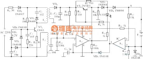
6.5V reference power supply circuit
Published:2011/4/14 6:46:00 Author:may | Keyword: 6.5V, reference power supply

This circuit can make DC voltage UV always stay at about 6.5V and has no reference to time and environmental temperature. Its main technical data:
Steady output voltage: UN=6.5±5% V
Output load current: IL=0~0.3mA
Input voltage (supply voltage) : U1=19~54V
Input current Ii (stable current Ia) : Ii=Ia≈2mA
Output resistor: dUN/dIN=r0=20Ω, maximum 50Ω
Voltage-regulation coefficient: dUN/dUI=a=3×10-6, maximum 3×10⁻⁵
When the range of environmental temperature is 0~70℃, the average temperature coefficient of reference voltage: SAV=-100~+140μV/grd, typical value +67μV/grd
Long term stability after working 100 hours: <1mV/1000 work hour
Environmental temperature: θu=0~70℃
(View)
View full Circuit Diagram | Comments | Reading(593)
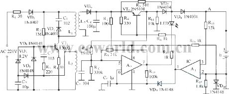
100v/10mA regulated voltage power supply circuit
Published:2011/4/20 1:17:00 Author:muriel | Keyword: 100v, 10mA, regulated voltage power supply circuit

Thecircuit has two functions that areno-load protection and shorttime short-circuit protection. If you want to allow short-circuit fora long time, it must increase the PCM of theresistance R1 and R2, such as R1=1.2KΩ, 20W; R2=220Ω, 4W.
The main technical data:
output voltage:U2=100V
output current:I2=10mA
input voltage:U1=120V~180V
Radiator thermal resistance:Rthk=20grd/W
output voltage variable quantity:
When input voltage U1=120V~180V and nominal load, ΔU2=1V
When input voltage U1=120V~180V andno-load, ΔU2=1.5V
When output current I2=0mA~10mA (U1=constant), ΔU2=1.5V
ambient temperature θu=0°C~60°C, ΔU2=150mV/grd
(View)
View full Circuit Diagram | Comments | Reading(1630)
Frequency modulation type switching stabilized voltage supply 2
Published:2011/4/19 4:02:00 Author:May | Keyword: Frequency modulation, switching, stabilized voltage supply

(View)
View full Circuit Diagram | Comments | Reading(491)
Reference voltage source using complementary transistors
Published:2011/4/14 6:44:00 Author:may | Keyword: Reference voltage source, complementary transistors


The characteristic of this circuit is shown in the following table ( RL=68kΩ)
reference voltage source
adopts BJT
adopts complementray transistor
voltage-regulation coefficient △U2/U1 ( enviromental termeprature θu=20 ℃)
1.2×10⁻⁴
4×10⁻⁵
variation of voltage reference △U2[when △U1/U1=(20±10)% and θu=20℃]
520μV
180μV
variation of voltage reference when the temperature rise from 20℃ to 100℃
9.6mV
10.8mV
output resistor
<15Ω
input rated voltage U1
22V
22V (View)
View full Circuit Diagram | Comments | Reading(468)
Reference voltage source using operational amplifier
Published:2011/4/14 4:38:00 Author:may | Keyword: Reference voltage source, operational amplifier

The features of this circuit:
1 operational amplifier will not cause drift, voltage regulator tube have thecharacteristic of temperature compensation
2 the output voltage of pin 3 is very low, so, output current must higher than 10mA, it has no influence to voltage regulator performance and drift characteristic
3 choosing appropriately among R1、R2 and R4 can make the output voltage has a wider range (U3>U2) . (View)
View full Circuit Diagram | Comments | Reading(527)
| Pages:244/291 At 20241242243244245246247248249250251252253254255256257258259260Under 20 |
Circuit Categories
power supply circuit
Amplifier Circuit
Basic Circuit
LED and Light Circuit
Sensor Circuit
Signal Processing
Electrical Equipment Circuit
Control Circuit
Remote Control Circuit
A/D-D/A Converter Circuit
Audio Circuit
Measuring and Test Circuit
Communication Circuit
Computer-Related Circuit
555 Circuit
Automotive Circuit
Repairing Circuit