power supply circuit
Index 243
MAX834 monitoring battery low voltage disconnection power supply circuit
Published:2011/4/22 4:58:00 Author:Nicole | Keyword: battery low voltage, power supply
View full Circuit Diagram | Comments | Reading(582)
Circuit Of Float-type Battery Charger
Published:2011/4/21 1:18:00 Author:Tina | Keyword: Float-type, Float-type Battery Charger
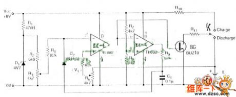
Figure 1 is one kind of Nickel-cadmium battery and Ni-MH battery charger circuit. This circuit is mainly used to charge the battery of nickel-cadmium and nickel metal hydride (5 #, 7 #). Charge mode is the power float type. The float means the power is continuous DC but not by the pulse voltage type. Battery float charge type is the most commonly way to charge the household batteries, the advantage is the simple circuit and the disadvantage is difficult to reach the battery's nominal capacity. This disadvantage is not obvious to the small-capacity rechargeable battery, but to the large capacity battery, this disadvantage will not only shorten the use time of battery, but also shorten the battery life, so to the large capacity battery such as the electric bicycle, we'd better not use the float charge type.
(View)
View full Circuit Diagram | Comments | Reading(1473)
TWL2213 typical application circuit(charging circuit)
Published:2011/4/22 4:29:00 Author:Nicole | Keyword: typical application, charging
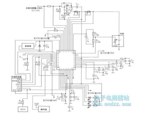
TWL2213 is mainly used to the power management of portable equipment or device such as PAD, telephone, pager which adopts lithium ion battery to supply power. The typical circuit diagram is shown as below:
(View)
View full Circuit Diagram | Comments | Reading(599)
Multi-channel regulated power supply composed of MC1568, LM309K
Published:2011/4/22 4:41:00 Author:Nicole | Keyword: regulated power supply
View full Circuit Diagram | Comments | Reading(665)
±12V regulated power supply composed of MC7812 positive pressure and MC7912MC(negative pressure)
Published:2011/4/22 4:16:00 Author:Nicole | Keyword: ±12V regulated power supply, positive pressure, negative pressure
View full Circuit Diagram | Comments | Reading(794)
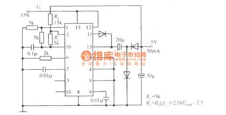
Polarity reversal boost power supply circuit diagram composed of LT1172
Published:2011/4/2 4:38:00 Author:Nicole | Keyword: boost power supply

As shown, this is a polarity reversal boost power supply which is composed of boost switching regulator LT1172. The output voltage is -10 ~-30V, output current is 25mA, conversion efficiency is 80%. It uses the LT1172 to boost, and connect a charge pump which composed of C1, C2, D2, D3 on the output termination of LT1172, then to complete the output voltage polarity reversal.
(View)
View full Circuit Diagram | Comments | Reading(1718)
Multi-Control Two Switch Circuit
Published:2011/4/21 20:18:00 Author:Robert | Keyword: Multi-Control, Two Switch Circuit

Multi-Control Two Switch Circuit is shown below:
(View)
View full Circuit Diagram | Comments | Reading(607)
±15V symmetric regulated power supply composed of LC1468G
Published:2011/4/22 3:08:00 Author:Nicole | Keyword: ±15V regulated power supply
View full Circuit Diagram | Comments | Reading(1689)
Power supply soft-start circuit composed of L200
Published:2011/4/22 3:12:00 Author:Nicole | Keyword: soft-start, power supply
View full Circuit Diagram | Comments | Reading(1560)
Improved TOP222P switching power supply module
Published:2011/4/21 5:51:00 Author:May | Keyword: Improved, switching, power supply module
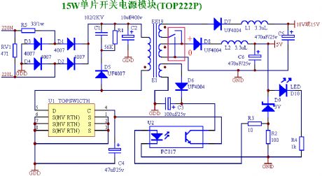
The AC input voltage of small switching power supply module using TOP222P chip is 100~245V. And it is two ways DC output. The largest DC output is 10v800mA(15v800mA)、5v800mA, the total output is less than 15W, power supply efficiency is 6%~85%. (Note 1: the output 5V group of this power module has the function of voltage regulation, another group output voltage can set like: it is 15V when connected with + , it is 10V when connected with 0 ).voltage accuracy: 4%;votlage adjustment rate: 0.7%;5V load adjustment rate: 1%;10V load adjustment rate: 8%;or 15V load adjustment rate: 10%;The size of small power supply module: length is 46mm, width is 28mm, height is 20mm.parts lists of small power supply module name quantityTOP222P chip 1EE19 transformer 1UF4007diode 1PC817 opto-coupler 13.3UH bead 23.6 voltage regulator diode 1471 voltage dependent resistor 110UF/400V electrolysis 1102/1KV ceramic chip 1470UF/25V electrolysis 1470UF/25V electrolysis 147UF/25V electrolysis 1100UF/25V electrolysis 1UF4004 diode 2IN4148 diode 1(can replace by UF4004 diode)1N4007diode 433/1W resistor 156K/0.25W resistor 110/0.25W resistor 1100/0.25W resistor 11K/0.25W resistor 13mmLED 1circuit wafer 1 (View)
View full Circuit Diagram | Comments | Reading(3783)
Pulse Battery Charger Circuit
Published:2011/4/21 7:02:00 Author:Christina | Keyword: Pulse, Battery Charger
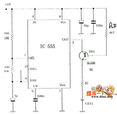
The Pulse Battery Charger Circuit is as shown:
(View)
View full Circuit Diagram | Comments | Reading(2209)
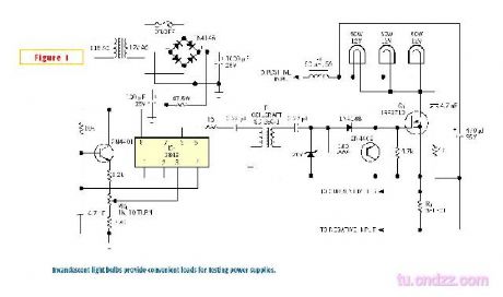
Common power supply load circuit with bulb
Published:2011/4/22 2:29:00 Author:Nicole | Keyword: power supply load, bulb
View full Circuit Diagram | Comments | Reading(614)
+5V 4W switching power supply circuit composed of single chip TOP210
Published:2011/4/21 2:21:00 Author:May | Keyword: +5V 4W, switching power supply
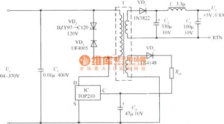
+5V 4W switching power supply circuit composed of single chip TOP210 is shown in the diagram. DC input voltage Ui is got after 85~265V AC rectifying and filtering. The voltage adjustment rate of this switching power supply is Sv=±1.5% (input DC voltage is 104~370V), load adjustment rate Si=±5% (load current changes from 10% to 100%), output ripples voltage is ±25mV. When the lead wire of Ui and TOP210 is shorter, it also can save IC. Clamping protection circuit consists of VDz and VD1. After the secondary voltage rectifying and filtering by VD2, C2, L and C3, it can get +5V, 0.8A output. Feed back winding first rectifying by VD3, than it is smoothed filtering by R and C4 and offer control end current to TOP210.
(View)
View full Circuit Diagram | Comments | Reading(2923)
Buck chopped wave switching regulated power supply circuit composed of CW1524
Published:2011/4/20 22:26:00 Author:May | Keyword: Buck, chopped wave switching, regulated power supply
View full Circuit Diagram | Comments | Reading(439)
Solar power supply equipment
Published:2011/4/21 8:17:00 Author:Nicole | Keyword: solar, power supply equipment

(a)photoelectric cell is in series, parallel; (b)adding diode VD, to avoid storage battery charging to photoelectric cell. (View)
View full Circuit Diagram | Comments | Reading(525)
Storage battery charger using capacitor to limit current and drop voltage
Published:2011/4/21 6:24:00 Author:May | Keyword: Storage battery charger, capacitor
View full Circuit Diagram | Comments | Reading(1173)
Storage battery automatic charger principle diagram
Published:2011/4/21 6:26:00 Author:May | Keyword: Storage battery, automatic charger
View full Circuit Diagram | Comments | Reading(919)
Solar battery charging circuit
Published:2011/4/21 6:27:00 Author:May | Keyword: Solar battery, charging
View full Circuit Diagram | Comments | Reading(1860)
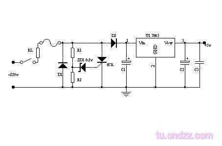
AC220V stabilivolt to DC5V Circuit
Published:2011/4/20 1:22:00 Author:muriel | Keyword: AC220V, stabilivolt, DC5V
View full Circuit Diagram | Comments | Reading(2203)
Digital control integrated regulated power supply
Published:2011/4/21 9:27:00 Author:Nicole | Keyword: regulated power supply, digital control
View full Circuit Diagram | Comments | Reading(517)
| Pages:243/291 At 20241242243244245246247248249250251252253254255256257258259260Under 20 |
Circuit Categories
power supply circuit
Amplifier Circuit
Basic Circuit
LED and Light Circuit
Sensor Circuit
Signal Processing
Electrical Equipment Circuit
Control Circuit
Remote Control Circuit
A/D-D/A Converter Circuit
Audio Circuit
Measuring and Test Circuit
Communication Circuit
Computer-Related Circuit
555 Circuit
Automotive Circuit
Repairing Circuit


