
Index 85
5_W_ATV_TRANSCEIVER
Published:2009/6/18 3:48:00 Author:May

For the transmitter schematic (part of this transceiver), see entry entitled S-W ATV Transmit-ter for 440 MHz, Fig. 5-1. The downconverter portion is shown here.This transmitter contains both a video and sound section. Five to six watts PEP on synch tips of NTSC video are produced. Three channels are available. Channel switching is via PIN diodes. Power supply voltage is 12 to 14 Vdc. The receiver function is provided with a downconverter circuit and is tunable. A relay is used for T-R switching. A complete kit of parts, including PC board, is available from North Country Radio, P.O.Box 53, Wykagyl Station, New Rochelle, NY 10804-0053A. (View)
View full Circuit Diagram | Comments | Reading(1922)
5_W_ATV_TRANSMITTER_FOR_440_MHz
Published:2009/6/18 3:45:00 Author:May

The circuit will produce typically 6 W RE output on synch tips. A crystal oscillator drives a doubler to produce a 220-MHz output.Another doubler produces 440 MHz to drive the power amplifier. A high-level series modulator provides the video modulation capa-bility. A sound subcarrier is generated using a VCO circuit and combined with the video information. A complete kit of parts, includ-ing the PC board, is available from North Country Radio, P.O.Box 53, Wykagyl Station, New Rochelle, NY 10804-0053A. (View)
View full Circuit Diagram | Comments | Reading(1608)
TV_SOUND_SYSTEM
Published:2009/6/18 1:43:00 Author:May

An LM2808 performs IF amplification of the 4.5-MHz sound subcarrier, limiting, detection, and audio amplification. If the center frequency must be changed, then change L1/C4. Audio out-put is 0.5 W. R3 is the volume control. (View)
View full Circuit Diagram | Comments | Reading(627)
HOME_SECURITY_SYSTEM
Published:2009/6/17 23:25:00 Author:May


At the heart of the main-control unit is U16, Zilog's Z8-8-bit microcontroller, which receives its program instruction from U17, a 27C64 8K x 8 EPROM. The home security system in its most basic form, features eight individual protection zones, adjustable entry and exit delays, a panic switch (for emergency situations), automatic system reset, support for an auto-dialer (which, in case of emergency, dials pre-programmed telephone numbers), it's X-10 compatible (allowing it to control house lights and ap-pliances), has a backup battery (to keep the system on-line during a power failure), and there is also an optional zone-status panel that is used to individually show the condition of each protection zone.This system's power supply provides 12 Vdc for the sirens and digital keypad, and 5 Vdc for the on-board electronics, while also providing a constant 12-V output that's used to charge the backup-battery. (View)
View full Circuit Diagram | Comments | Reading(32)
PULSE_GENERATOR_WITH_VARIABLE_DUTY_CYCLE
Published:2009/6/17 21:59:00 Author:May
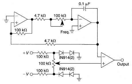
Using only one IC and six passive components, this pulse generator has a frequency range of 400 to 4000 Hz and an adjustable duty cycle of 1 to 99%. A threshold detector (ICA) and an in-tegrator (ICB) generate a triangular waveform. A positive voltage at the output of ICA causes the output of ICB to become a negative-going ramp. When the output of this ramp reaches a certain value, ICA, by virtue of its positive-feedback net-work, changes state; its output becomes nega-tive, and the integrator generates positive ramp.This process continually repeats. A voltage fol-lower (ICC) and a 100-kO potentiometer provide a variable ±18-V reference voltage. This reference voltage, along with the triangular waveform, feeds into the positive and negative inputs, respectively, of comparator ICD. You can set the comparator's trip voltage at any point on the triangular waveform; ICD's output changes at that point. Varying the reference voltage alters the duty cycle of the comparator's output by adjusting the potentiometer at the negative input of the integrator, thereby varying the integration time without altering the duty cycle. (View)
View full Circuit Diagram | Comments | Reading(1906)
PRECISE_ONE_SHOT
Published:2009/6/17 21:28:00 Author:May


This approach uses a flip-flop, a shift register, and two gates (A). Before the one-shot pulse, the output of the NOR gate is 0. Consequently, the data input of the D-type flip-flop is equivalent to the trigger. When a trigger pulse is present, the flip-flop initiates the one-shot pulse, and the n-stage shift register controls the pulse width, tw , which is a multiple of the clock's period (B).The precision of the one-shot pulse is determined by the clock period, which is inversely pro-portional to its frequency. For the circuit to work properly, the width of the trigger pulse, twt, should be greater than one clock period.The OR gate masks the trigger's effect when the circuit is generating the desired pulse. The net result is a circuit that functions as a nonretriggerable rrtultivibrator.When the pulse needs to be only one-clock-period wide, the circuit can be simplified. All that's required are two D-type flip-flops and an AND gate. However, despite its simplicity, this circuit generates a more stable and precise one-shot pulse than a multivibrator. (View)
View full Circuit Diagram | Comments | Reading(1302)
ELECTRONIC_SCALE
Published:2009/6/17 4:05:00 Author:May

An electronic scale using a pressure transducer Goad cell) and an analog-digital (A/D) converter to drive a digital display is shown. The scale range depends on load cell. Display is calibrated in appropriate units. Components are on main circuit and display boards. The off-board controls are on the front panel and case. The cell in this scale is rated for 1.3 pounds (600 grams). (View)
View full Circuit Diagram | Comments | Reading(6075)
RC_DECADE_BOX
Published:2009/6/17 4:01:00 Author:May


THE VARIOUS CONFIGURATIONS are set using S13: (a) resistor only and (b) capacitor only (both in position R/C); (c) series RC (position SER); (d) parallel RC (position PAR); (e) Low-Pass Filter (position LPF); and (f) High-Pass Filter (position HPF). The terminal numbers listed are those of bindinq-oosts BP1-BP6.
This decade box can be set for any resistance value between 10 Ω and 11.1 MΩ in 10-Ω stops. A switch can be used to configure several RC configurations. Use close tolerance components in the circuit. Ifpossible, check components with an accurate bridge or other means to ensure accuracy. (View)
View full Circuit Diagram | Comments | Reading(2691)
ELECTRONIC_SLOT_MACHINE
Published:2009/6/17 3:50:00 Author:May

The slot machine's realistic action is provided by seven ICs and three displays, as shown. Two 555 CMOS timer ICs ge;terate pulses. IC1 is used to generate the clock pulses for the entire electronic slot machine. The pulses are coupled from the output (pin 3) to the clock inputs of IC4, IC5, and IC6, the display-driver ICs.
The displays are common-cathode 7-segment LED types. They are wired to display three different symbols, an L, a 7, and bar. When all three displays show the same symbols, IC7 (a 4023 triple 3-input NAND gate) decodes a winner and sends a signal to pin 5 of IC3. That IC is a 4001 CMOS NOR gate and it turns on IC2, a 555 timer IC. IC2 actually produces the winner tone on its output, pin 3.
Transistors Q4 through Q12 are used to drive the common-cathode displays. An LED is used to indicate the clock pulses, and a variable resistor is provided for each of these functions. Trimmer resistor PI controls the overall clock rate, P2 controls the winner tone, and P3 controls the display brilliance. (View)
View full Circuit Diagram | Comments | Reading(3120)
PRINTER_SENTRY
Published:2009/6/17 3:09:00 Author:May


Handy for monitoring printers, this circuit displays all the signals on a parallel link. It monitors the status of the lines, enabling remote monitoring of the operation of a printer, and it also gives an indication of troubles (paper empty, busy, etc.). (View)
View full Circuit Diagram | Comments | Reading(616)
MICROCOMPUTER_TO_TRIAC_INTERFACE
Published:2009/6/16 23:16:00 Author:May

A microcomputer-to-triac interface uses a phototriac optoisolator to let safety-isolated logic sig-nals directly control high-power loads. Depending on the input waveforms and the load, this circuit can be used in either an on/off switch or a proportional phase control. A low input powers the lamp. (View)
View full Circuit Diagram | Comments | Reading(1624)
RECEIVER_INTERFACE_CIRCUIT_FOR_PREAMPS
Published:2009/6/16 23:05:00 Author:May

The purpose of the receiver/interface circuit is to pass RF to the receiver through capacitor C9, while adding dc power to the feedline through R2 and RF choke L7. (View)
View full Circuit Diagram | Comments | Reading(428)
RELAY_INTERFACE_FOR_AMATEUR_RADIO_TRANSCEIVERS
Published:2009/6/16 23:05:00 Author:May

The relay power ln the linear IS obtained from the -120-V bias supply,and the transmit keving output from the Kenwood is+12 V at 10 mA maximum,The key ingredient in the circuit is the pnp driver transistor,which must be capable of handling at least 150 V at about 250 mA (View)
View full Circuit Diagram | Comments | Reading(667)
PROCESS_CONTROL_INTERFACE
Published:2009/6/16 23:02:00 Author:May

This circuit can be used to interface a 2-wire transmitter/sensor combination to an external de-vice or measurement setup. (View)
View full Circuit Diagram | Comments | Reading(563)
AUDIO_TO_ADC_INTERFACE
Published:2009/6/16 23:02:00 Author:May

This simple general-purpose driver for an analog/digital converter uses two 741 IC devices with adjustable gain and offset. Other op amps might be substituted, but some circuit adjustments might beneeded. (View)
View full Circuit Diagram | Comments | Reading(3321)
TELEPHONE_INTERCOM
Published:2009/6/16 22:59:00 Author:May

An intercom using dual-modular wall jacks is shown in this circuit. If the wires are available in the home telephone cable, this system can be installed with little trouble. (View)
View full Circuit Diagram | Comments | Reading(1037)
VERY_SIMPLE_TELEPHONE_INTERCOM_CIRCUIT
Published:2009/6/16 22:58:00 Author:May

Tro telephones can be used as an intercom by using this circuit. Older style rotary phones that are nonelectronic might work best in this application. Also, handsets only might be powered this way. (View)
View full Circuit Diagram | Comments | Reading(3319)
THE_TALKING_COMPASS
Published:2009/6/16 22:00:00 Author:May

A talking compass is made up using a Hall-effect direction sensor (MOD1) and an ISD1016 analog audio storage device. It is possible to program eight two-second announcements, for each of the eight main compass directions.The Talking Compass is comprised of a digital compass (MOD1), and ISD1016 analog storage de-vice (U2), a 74S188 preprogrammed PROM (U3), and a handful of additional components. (View)
View full Circuit Diagram | Comments | Reading(1787)
ENGINE_BLOCK_HEATER_MINDER
Published:2009/6/16 2:42:00 Author:May
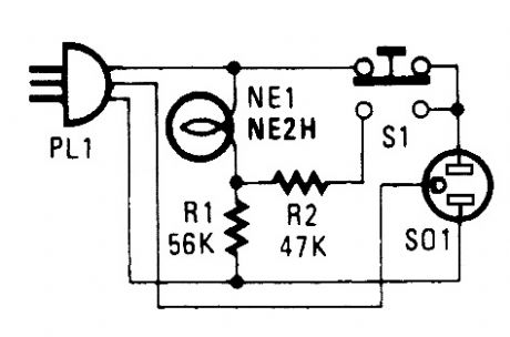
If you live in the frozen north, knowing your engine-block heater is working is a comfort. This device will let you know if yours is okay. Plug in PL1 to your power outlet. NE1 should light.Then, plug in the block heater. Depressing S1 should cause the indicator to get brighter. If not, your block heater might be open and inoperative. (View)
View full Circuit Diagram | Comments | Reading(633)
AMPLIFIED_FIELD_STRENGTH_METER
Published:2009/6/16 2:11:00 Author:May

FET Q1 acts as an RF amplifier to boost sensitivity of the usual diode detector field strength meter. (View)
View full Circuit Diagram | Comments | Reading(2142)
| Pages:85/126 At 2081828384858687888990919293949596979899100Under 20 |
Circuit Categories
power supply circuit
Amplifier Circuit
Basic Circuit
LED and Light Circuit
Sensor Circuit
Signal Processing
Electrical Equipment Circuit
Control Circuit
Remote Control Circuit
A/D-D/A Converter Circuit
Audio Circuit
Measuring and Test Circuit
Communication Circuit
Computer-Related Circuit
555 Circuit
Automotive Circuit
Repairing Circuit