
Index 82
VARACTORLESS_HF_MODULATOR
Published:2009/6/23 4:36:00 Author:Jessie

Traditionally, high-frequency oscillators are frequency-modulated by using a varactor. However, varactors usually require a large voltage change to achieve a reasonable capacitance change-a prob-lem in many battery-powered systems.Such a problem can be overcome by employing base-charging capacitance modulation. Resistor RI establishes Q1's current, and R2 allows control of the collector bias current byVmod The trans-mission line (T1) in the negative resistance-type oscillator determines the frequency of oscillation. T1 is a high-quality, low-loss, ceramic coaxial shorted quarter-wave transmission line. Under proper terminal impedances, a negative resistance is seen at Q1's base. T1 reacts with this negative resis-tance to produce sustained oscillations.Frequency modulation is accomplished by changing Q1's collector bias current and thus chang-ing Q1's base-charging capacitance. This effect is seen at Q1's base and causes a frequency shift in the resonators quarter-wave node. (View)
View full Circuit Diagram | Comments | Reading(1251)
MODEL_RAILROAD_CROSSING_FLASHER
Published:2009/6/23 4:27:00 Author:Jessie

Gate U1-c is set up as an oscillator whose frequency is determined by C1 and R1. Gates U1-b and U1-d are set up as an RS flip-flop that is gated on by U1-a. Gate U1-a in conjunction with Q1 operates as the control gate for the flip-flop. Components D1, C2, and lR5 act as a delay circuit to compensate for anylight getting throughthe gaps between cars as theypass over the phototransistors. The light-emitting diodes are connected so that they operate alternately, depending on the outputs of U1-d and U1-b.Basically, R6 is adjusted so that ambient room-light striking Q1(and any other phototransistors connected in series)keeps the output of U1-a at pin 3 low. When a car passes over the phototransis-tor, which is installed between ties in the track, pin 3 goes high, allowing a high to be placed on pins 5 and 13. That allows the high output of UI-c at pin 10 to enable pin 12, which in turn allows pin 11 to go low. That makes a complete path for LED2 to operate. When pin 10 goes low, pin 11 goes high.That makes pin 5 high, and thus, enables pin 4 to go low and completes the circuit for LED1. That alternates the LEDs, which are installed in a railroad-crossing signal. (View)
View full Circuit Diagram | Comments | Reading(0)
Electronic hypnotic device 3
Published:2011/7/29 3:01:00 Author:Ecco | Keyword: Electronic, hypnotic device

This example describes a simple electronic hypnosis device circuit, it has less circuit components,and it iseasy to make.
The working principle.
The electronic hypnosiscircuit is non-steady-state multi-harmonic oscillator circuit which is composed ofthe time base ICand relatedexternal components, it is shown in Figure 9-140.
After turning on power switch S, +6 V voltage is applied to 4 feet and 8 feet of IC to provide power supply for the IC. After multivibrator oscillation, the pin 3 of IC outputs low-frequency oscillation pulse signal, and it is combined by the capacitor C2 and added to the speaker BL, then it issues the simulated sound of dripping water. The voice has hypnotic effects for insomnia. Adjusting potentiometer RP can change capacitor Cl and the operating frequency of multivibrator. The selection of componentsR selects 1/4W carbon film resistor. RP uses small solid potentiometer or sealed variable resistor. Cl and C2 select the electrolytic capacitor with voltage in lOV. IC uses NE555 or μA555, LM555, 5G1555, FX555 and other models of time-base integrated circuits.
(View)
View full Circuit Diagram | Comments | Reading(3195)
Electronic hypnotic device 4
Published:2011/7/29 2:43:00 Author:Ecco | Keyword: Electronic , hypnotic device

The electronic hypnotic device described in the example can generate simulated sound of dripping water and be used for the treatment for insomnia.
The working principle.
The electronic hypnotic deviceis composed of the oscillator circuit, boost charging circuit and the rain sound formation circuit, it is shown in Figure 9-141.
Oscillator circuitis composed of the battery GB, control button S, transistor V, potentiometer RP, resistor Rl and Wl, W2 windings of oscillation transformer T.
Boost charging circuitis composed of the W3 winding of T, rectifier diode VD and capacitor C.
The sound of raindrops forming circuit is composed of resistors R2-R5, neon lights HLl-H4 and buzzer HAl-HA4.
R1-R5 select 1/4W metal film resistors.
RP uses multi-turn wirewound potentiometers.
C usesaluminium electrolytic capacitor with the voltage in 400V, the leakage is aslowas possible.
VD selects lA, l0OOV rectifier diode.
V uses 3AX31 germanium PNP transistor.
HAl-HA4 use HTD-27A piezoelectric buzzer with help tune. (View)
View full Circuit Diagram | Comments | Reading(1007)
VIDEO_MASTER
Published:2009/6/23 3:58:00 Author:Jessie

The video master consists of a series of converters that place all your video sources on unused UHF channels, which then combines them with normal TV channels (terrestrial or cable into one ca-ble). That one cable can then feed several TV sets for whole-house coverage. The desired video source is selected with the TV set's tuner. All of the TV's remote-control features are retained.A complete kit of parts is available from North Country Radio, P.O. Box 53, Wykagyl Station, New Rochelle, NY 10804-0053A. (View)
View full Circuit Diagram | Comments | Reading(1173)
SIMPLE_AUDIO_MIXER
Published:2009/6/23 3:45:00 Author:Jessie

A single transistor is used as an audio mixer, the transistor serving as a feedback amplifier. (View)
View full Circuit Diagram | Comments | Reading(996)
TV_HORIZONTAL_DEFLECTION_CIRCUIT
Published:2009/6/23 2:34:00 Author:May

The circuit illustrates the method of using two SCR devices in a TV horizontal deflection application. This circuit was widely used by certain TV manufacturers as an alternate to the vacuum tube or transistor deflection circuit. (View)
View full Circuit Diagram | Comments | Reading(3245)
ELECTRONIC_FISH_LURE
Published:2009/6/23 2:56:00 Author:Jessie

The click-click sound lures fish to the vicinity, where your bait or lure can do the rest. The trans-former is a subminiature type with a 500-Q, center-tapped primary and a 3.2-Q secondary. Put the circuit in a watertight container and lower it into the water. (View)
View full Circuit Diagram | Comments | Reading(191)
PHOTO_SUPER_STROBE
Published:2009/6/23 2:55:00 Author:Jessie

A change in audio or light level on the sensor connected to J1 is amplified by IC1-a and IC1-b (rectified), and used to trigger IC2. R12 sets the delay between the trigger and the flash. IC1-c drives indicator LED2 and triggers SCR1, which sets off the strobe connected to J2. A photo cell or a microphone can be used as a sensor. (View)
View full Circuit Diagram | Comments | Reading(662)
SLIDE_STEPPER
Published:2009/6/23 2:53:00 Author:Jessie

This stepper circuit replaces remote controls and will automatically advance slides in a projector.The time delay is variable with R4. The cable connections are for a Kodak carousel slide projector. (View)
View full Circuit Diagram | Comments | Reading(1481)
CHARGER_FOR_PHOTOFLASH_CAPACITOR
Published:2009/6/23 2:51:00 Author:Jessie

This circuit charges photoflash capacitor C (480μF, 500 V) for photoflash usage. (View)
View full Circuit Diagram | Comments | Reading(528)
1_dB_PAD
Published:2009/6/23 2:03:00 Author:Jessie

The 1-dB pad is useful as a termination in RF work to limit possible mismatch range between system blocks, etc. (View)
View full Circuit Diagram | Comments | Reading(970)
AUDIO_MIXER
Published:2009/6/23 1:49:00 Author:Jessie

The 741 op amp is used as a summing amplifier to combine several audio inputs. Overall gain is set by Rf. (View)
View full Circuit Diagram | Comments | Reading(3)
SUBAUDIBLE_TONE_ENCODER
Published:2009/6/23 1:48:00 Author:Jessie

This twin-T oscillator produces six preset subaudible tones from 93 to 170 Hz in three ranges. (View)
View full Circuit Diagram | Comments | Reading(0)
CODE_PRACTICE_OSCILLATOR_1
Published:2009/6/23 1:46:00 Author:Jessie

Oscillator, works with 2 to 12 Vdc (but 9 to 12 volts gives best volume and clean keying). R1 can be replaced with a 500 K pot and the circuit wili sweep the entire audio frequency range. (View)
View full Circuit Diagram | Comments | Reading(1398)
REMOTE_RE_CURRENT_READOUT
Published:2009/6/23 1:45:00 Author:Jessie
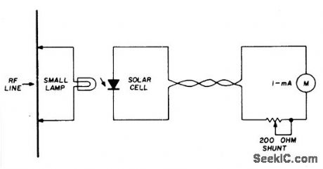
A suitable pilot lamp is illuminated by a small sample of rf and energizes an inexpensive solar cell; the dc current generated by the cell is a measure of relative rf power, and may be routed to a low-current meter located at any convenient point. A sensitive, low-current pilot lamp is desirable to cause minimum dis-turbance to normal rf circuit conditions. The number 48 or 49, 60 mA lamp is suitable for use with transmitters above 1-watt output. (View)
View full Circuit Diagram | Comments | Reading(1169)
SELF_POWERED_CW_MONITOR
Published:2009/6/23 1:44:00 Author:Jessie

Position L near the transmitter output tank to hear the key-down tone。Then tape the coil In place. C=.047μF,R=8.2 K,Q=HEP 253(or equal),T=500:500 ohm center tapped transformer. L = 2 to 6 turns on 1/2'' coil from. (View)
View full Circuit Diagram | Comments | Reading(0)
AUTOMATIC_TAPE_RECORDING
Published:2009/6/23 1:42:00 Author:Jessie

Amateurs don’t haveto missthe action while away from the tug.This circuit turns on a tape recorder whenever the recelver’s squelch IS broken. After signal loss, the recorder will shut off following a slight delay. (View)
View full Circuit Diagram | Comments | Reading(1034)
CODE_PRACTICE_OSCILLATOR
Published:2009/6/23 1:41:00 Author:Jessie

This simple cpo uses the 7404 low-power Schottky hex inverter. C is a 5- to 30-μF electrolytic selected for the desired pitch. The speaker is a 2-inch, 8-ohm unit. (View)
View full Circuit Diagram | Comments | Reading(452)
ELECTRONIC_KEYER
Published:2009/6/23 1:40:00 Author:Jessie

This circuit automatically produces Morse code dots and dashes set by time constants involving C1 and C2. R1 sets dot/dash ratio and R2 sets the speed. R5 sets the relay drop-out point. (View)
View full Circuit Diagram | Comments | Reading(949)
| Pages:82/126 At 2081828384858687888990919293949596979899100Under 20 |
Circuit Categories
power supply circuit
Amplifier Circuit
Basic Circuit
LED and Light Circuit
Sensor Circuit
Signal Processing
Electrical Equipment Circuit
Control Circuit
Remote Control Circuit
A/D-D/A Converter Circuit
Audio Circuit
Measuring and Test Circuit
Communication Circuit
Computer-Related Circuit
555 Circuit
Automotive Circuit
Repairing Circuit