
Light Control
Index 2
Car light flashing circuit composed of 555, CD4017B
Published:2011/11/3 21:31:00 Author:May | Keyword: Car light flashing, 555
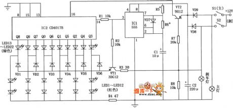
Car light flashing circuit mainly consists of red, green lights. When it emits light,red light islighten from middle to end, and green light jumps from end to middle. When car drives normally, red light and green light arelighten according to program order. When it is braking, all green lights die out, but all red light are lighten. Car light flashing circuit is shown in the diagram.
(View)
View full Circuit Diagram | Comments | Reading(2676)
Electronic touch dimmer circuit composed of CD4028
Published:2011/11/9 21:47:00 Author:May | Keyword: Electronic touch dimmer
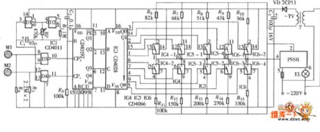
The diagram is touch dimmer which uses a kind of parameters of solid state relays (PSSR) as main control component, and it is not normally used bidirectional thyristor. The light adjusting process uses touching method,and itis convenient, and the circuit is shown in the diagram. This circuit consists of touch control signal input circuit, stepper control pulse generator, pulse / down counter, pulse signal decoding distributor, ten control parameters of solid-state switches and relays, etc.
(View)
View full Circuit Diagram | Comments | Reading(2805)
Circuit diagram of controlling groups of light by one single switch
Published:2011/9/7 1:25:00 Author:Vicky | Keyword: controlling, lingt, single switch

As shown in the above circuit diagram, when the power switch K is conducted for the first time, 1# light illumines at once. Because voltage of the capacitor C3 would not change suddenly, the photo-coupler G is conducted only at the moment that switch K is conducted. But soon G stops. In addition, saltation does not occur to the voltage of the capacitance C4, so silicon controlled rectifier S1 would not be conducted (C1 hasn’t generated voltage at the moment of the connection of K, likewise, S2 would not be conducted). Therefore, 2# and 3# light would not lighten. (View)
View full Circuit Diagram | Comments | Reading(1177)
A Passive Light-controlled Switched Circuit Diagram
Published:2011/9/3 19:59:00 Author:Zoey | Keyword: Passive, Light-controlled, Switched Circuit Diagram
Following picture shows the passive light-controlled switched circuit. Generally, light-controlled switches need power supply. Although integrated light-controlled controllable silicon switches do not need power supply, they have to satisfy the requirements such as high sensitivity and high pressure resistance. Circuit (a) is a passive light-controlled direct current switch, therein, 2CR1 and 2CR2 are closed gate high-speed light cell, they are used to receive light signals, produce voltage and input current. Circuit (b) is a passive light-controlled AC switch, if the load current is not large enough, it can set the load on AC trigger directly and it can work without the AC trigger.
(View)
View full Circuit Diagram | Comments | Reading(640)
MPY100 Division circuit
Published:2011/8/19 1:41:00 Author:Jessie | Keyword: Division

This circuit is composedof multiplier-division integrated circuit MPY100. Input signals are V1, V2, output Vo is: Vo=10V2/V1. This kind of division is composedof multiplieraccessed tofeedback loop of op-amp. V1's input range is -0.2 V to 10V, V2's input range is -10 V to 10V. Circuit's error is bigger, whenV1 is very small. (View)
View full Circuit Diagram | Comments | Reading(691)
The circuit diagram of a load-driving multiplier (MPY600)
Published:2011/8/9 2:57:00 Author:Felicity | Keyword: load-driving multiplier


The circuit of a load-driving multiplier consists of multiplier MPY600 and high speed cache OPA633 is shown in fig(a). The relationship between input and output : Vo=VxVy/2. The voltage output by high speed cache OPA633 can drive capacitive load.MPY600 is wide bandwith multiplier, and the features are:1 High bandwidth: current output:75MHz, voltage output 30MHz2 Low noises3 Low feedthrough4 The datum output is GND5 Low misalignment voltage.
(View)
View full Circuit Diagram | Comments | Reading(776)
choosing operation mode by the input terminal adding and subtraction circuit
Published:2011/7/27 8:21:00 Author:Fiona | Keyword: input terminal, adding, subtraction, operation mode


Circuit function
This is the PSD of match using silicon photodiodes.In order to reduce the error because of receiving flux,it usually carries out the operation A + B, and thus to control the laser diode power. This circuit uses the common circuit module that can add and subtract, which has 3 inputs, but has different functions,for example, only the A and B input, it's a common additive A + B circuit; if it uses C to input and uses one between A and B,you can subtract.
Circuit Work
This addition and subtraction circuit is composed of the inverse OP amplifier circuit, the output voltage EO can express by the following formula:
Under this formula, if assuming the resistance R1 ~ R6 are equal, you can to do the addition and subtraction operations that the magnification is 1.
In the inverting amplifier, the input resistor is the input impedance, if it needs high input resistance, OP amplifier should be replaced by BI-FET type, such as the TL082, etc., and removes the resistors R7, R8. (View)
View full Circuit Diagram | Comments | Reading(659)
The circuit diagram of multiplication circuit 2 (MPY100)
Published:2011/8/6 0:14:00 Author:Felicity | Keyword: multiplication circuit


The increase of the factor of proportionality causes the Offset Voltage to rise, and this need zero modulation. Besides it can narrow the bandwidth. The figure shows the circuit diagram of multiplication circuit 2 (MPY100). Main parameters of MPY100: (View)
View full Circuit Diagram | Comments | Reading(692)
Light Control Cockcrow Ciruit
Published:2011/8/4 2:42:00 Author:May | Keyword: light control, cockcrow
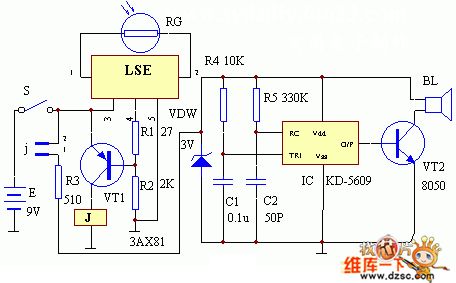
The circuit working principle of this set is shown in the diagram. At night, when there is no light shining on the photoresistor RG, the essential resistance of RG is very large, (larger than 50K) , so LSE's pin ①, ② is equal to open, LSE's pin ④ outputs low level, triode VT1 is break over, relay J excitation actuation, its normal close point j is opened, analog cockcrow circuit IC KD5609has no power and does not work. When daybreak, there is light shine on RG, the essential resistance of RG changeslower ( <50k) , at this moment , LSE' pin ④ outputs high level, triode VT1 is closed, relay J is released, its normal close point j is closed, analog cockcrow circuit is electrified and worked, andit sends clearly crow from the indicator speaker BL.
(View)
View full Circuit Diagram | Comments | Reading(713)
LINE_OPERATED_POWER_OUTAGE_LIGHT
Published:2009/7/8 22:48:00 Author:Jessie
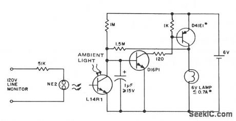
This circuit provides emergency lighting during a power outage. The phototransistor should be positioned to maximize coupling of both neon light and ambient light into the pellet, without allowing self-illumination from the 6-V lamp. Many circuits of this type also use line voltage to charge the battery.
(View)
View full Circuit Diagram | Comments | Reading(917)
AUTOMATIC_LIGHT_CONTROLLER_FOR_CARPORT
Published:2009/7/1 1:15:00 Author:May

A 555 timer IC, operating in the one-shot mode, is triggered by light striking photoresistors. These normally have a resistance of several megohms but, in the pres-ence of light, that resistance drops to several hundred ohms, permitting current from the six-volt source to flow in the circuit. The R-C combination shown gives an on-time of about two minutes. Photoresistors PC3 and PC4 are mounted at heatlight-height. When headlights illuminate the photoresistor, the timer starts. That actuates a relay, RY1, and the lights are turned on. The lights are automatically turned off when the timer's two minutes are up. (View)
View full Circuit Diagram | Comments | Reading(922)
Traditional op-amp inverting attenuator circuit
Published:2011/7/28 4:16:00 Author:John | Keyword: op-amp, inverting attenuator

Traditional op-amp inverting attenuator circuit is shown.
(View)
View full Circuit Diagram | Comments | Reading(2221)
The motor vehicle headlight auto-dimming controller 5
Published:2011/8/1 2:49:00 Author:Ecco | Keyword: motor vehicle, headlight, auto-dimming , controller

The motor vehicle headlight auto-dimming controller described in the example can automatically change the high beam into low beam at night, it improves the safety of driving at night.The working principle.The vehicle headlight auto-dimming controller circuit consists of photoresistor RG, electronic switch IC, potentiometer Rp, resistor R, the relay K, diode VD and other components, the circuit is shown as the figure 7-5.
Turning on the headlamp control switch S, RG is in a high impedance state due to no light exposure, the pin 2 of IC is in high potential, their internal electronic switch is off, pin 4 outputs high potential, K is in free state, the normally open contact is open, normally closed contact is connected, high beam EL2 is lit.
R chooses 1/2W metal film resistor or carbon film resistors.
RP selects small organic solid potentiometer.
RG uses a photosensitive resistor with light resistancebeing less than or equal to lOkΩ, dark resistancebeing greater than 5OOkΩ.
VD uses lN4007 silicon rectifier diode.
IC selects TWH8751 high-power electronic switching circuit.
K selects a l2V or 24V (supply voltage is according to motor vehicle) small DC relay.
(View)
View full Circuit Diagram | Comments | Reading(1731)
COMPLE_ME_NTARY_LIGHTING_CONTROL
Published:2009/6/25 1:43:00 Author:May

This lighting-control unit will fade out one lamp while simultaneously increasing the light output of another. The two loads track each other accurately without adjustments. The gate of SCR1, a silicon-controlled rectifier, is driven from a standard phase-control circuit, based, for example, on a unijunction transistor or a diac. It controls the brightness of lamp L1 directly. Whenever SCR1 is not on, a small current flows through L1, D1, and R1, permitting SCR2 to fire. When SCR1 turns on, current flow ceases through D1 and R1; the energy stored in C1 produces a negative spike that turns SCR2 off. (View)
View full Circuit Diagram | Comments | Reading(633)
The automatic control circuit diagram of vestibular light with photocoupler
Published:2011/3/30 22:53:00 Author:Ecco | Keyword: automatic control, vestibular light , photocoupler
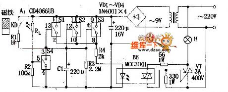
According to the circuitry, A stands for four sets of analog electronic switches(S1~S4: the parallel connection of S1,S2,S3 is used as time-delay circuit, which could increase the driving power and anti-interference capability. When they are connected to the power, and they could control vestibular light H directly by bidirectional triode thyristor VT with driving of R4,B6; S4 and light dependent resistor Rl. etc composed environmental light measuring circuitry. When the door is closed, the reed KD in the door will influenced by magnet, its contacts will be disconnected, and S1, S2, S3 are in the state of ON . When in the night, the host come back and open the door, the magnet will separated from KD, and the contacts will be connected. At the same time, the 9V supply will charge C1 by passing R1, the voltage in two terminals rise to 9V quickly, and commutating voltage passes S1,S2,S3 and R4 to make B6 lighted and bidirectional triode thyristor breakovered. H is lit. That is torealize automatic control. When the door in closed, the magnet will make the contacts of KD disconnected, and 9v supply will stop charging for C1, the circuitry is in the time-delay state. C1 begin discharges to the R3, after a period of time delay, the two terminal voltage of C1 will lower than opening voltage(1.5V) of S1,S2,S3, and they will recover the disconnected state, and B6 and H stop working. That is to realize the function of turning off a lamp while postponing.
(View)
View full Circuit Diagram | Comments | Reading(622)
SELF_LATCHING_LIGHT_ACTIVATED_SWITCH
Published:2009/6/17 2:40:00 Author:May

When light strikes the CDS cell it turns on the transistors which activates the relay which latches. Depressing 51 grounds the base of the 2N3565 and the relay resets. The 250 k potentiometer adjusts the sensitivity of the circuit. (View)
View full Circuit Diagram | Comments | Reading(1078)
PRECISION_LIGHT_SENSITIVE_RELAY_SWITCH
Published:2009/6/17 2:40:00 Author:May

A CDS cell in a bridge circuit with an op amp provides a simple means of operating a relay at a predetermined light level. Potentiometer R4 sets the sensitivity. (View)
View full Circuit Diagram | Comments | Reading(1025)
PORCH_LIGHT_CONTROL
Published:2009/6/17 2:33:00 Author:May

This circuit can control the on/off cycle of a light via a CDS photocell, and turn it off after a pre-set period. The light can only be turned on when CDS cell is in darkness, and it stays on for a time determined by the 555 circuit. On time depends on RI and C1 and is about 80 seconds with the values shown. (View)
View full Circuit Diagram | Comments | Reading(1015)
OUTDOOR_LIGHT_CONTROLLER
Published:2009/6/17 2:31:00 Author:May

A neon bulb and a CdS photocell enclosed in a light-tight enclosure forrn an optocoupler. A diac/triac combination is used to provide the snap-switch effect. A second CdS photocell acts as the main sensor.
As darkness approaches, the resistance of R4 begins to increase. At a threshold level, the diac triggers the triac and causes the neon bulb to light. This reduces the resistance of R6, causing the diac to trigger the triac, which lights the neon bulb and provides power to the load.As moming light comes up, the process is reversed. The neon bulb goes out and the SCR turns off. (View)
View full Circuit Diagram | Comments | Reading(1461)
CMOS_TOUCH_DIMMER
Published:2009/6/17 2:13:00 Author:May

A Seimens SLB0586A IC allows the construction of a simple touch-controlled dimmer circuit.The circuit controls a triac ac switch,which allows control of loads from 10 to 400 W. (View)
View full Circuit Diagram | Comments | Reading(3102)
| Pages:2/5 12345 |
Circuit Categories
power supply circuit
Amplifier Circuit
Basic Circuit
LED and Light Circuit
Sensor Circuit
Signal Processing
Electrical Equipment Circuit
Control Circuit
Remote Control Circuit
A/D-D/A Converter Circuit
Audio Circuit
Measuring and Test Circuit
Communication Circuit
Computer-Related Circuit
555 Circuit
Automotive Circuit
Repairing Circuit