
Light Control
Index 4
bridge amplifier circuit with a low-noise compensation circuit
Published:2011/5/15 2:02:00 Author:John | Keyword: low-noise compensation circuit, bridge amplifier

bridge amplifier circuit with a low-noise compensation circuit
(View)
View full Circuit Diagram | Comments | Reading(973)
non-inverting AC amplifier circuit
Published:2011/5/15 2:59:00 Author:John | Keyword: AC amplifier

Non-inverting AC amplifier circuitis shown below.
(View)
View full Circuit Diagram | Comments | Reading(3131)
inverting amplifier with high input impedance circuit
Published:2011/5/15 2:38:00 Author:John | Keyword: inverting amplifier

Inverting amplifier with high input impedance circuit is shown below.
(View)
View full Circuit Diagram | Comments | Reading(1915)
Two-State Touch Light Control Circuit
Published:2011/4/30 19:53:00 Author:Robert | Keyword: Two-State Touch, Light Control


Picture (a) shows the 220V single-wire application circuit.
Picture (b) shows the 220V two-wire application circuit.
Picture (c) shows the 110V single-wire application circuit.
Picture (d) shows the 110V two-wire application circuit.
(View)
View full Circuit Diagram | Comments | Reading(2747)
Toilet automatic lighting switch circuit composed of CD4022
Published:2011/4/24 1:20:00 Author:May | Keyword: Toilet automatic lighting switch

The diagram is Toilet automatic lighting switch which uses gate control type, when someone enter, the door open once, lighting switch breakover, the lamp is lightening. When someone go out the door and open it again, switch cut off and go out. The circuit network is shown in the diagram. The circuit consists of Hall switch, octal count, pulse distributor CD4022 and bidirectional thyristorVTH.
(View)
View full Circuit Diagram | Comments | Reading(2930)
Light Control Street Lamp Circuit Using TWH8778
Published:2011/4/26 5:53:00 Author:Robert | Keyword: Light Control, Street Lamp
View full Circuit Diagram | Comments | Reading(735)
Touch Dimmer Circuit Composed Of LS7232
Published:2011/4/26 5:54:00 Author:Robert | Keyword: Touch, Dimmer

Touch Dimmer Circuit Composed Of LS7232 is shown below:
(View)
View full Circuit Diagram | Comments | Reading(3564)
Light Control Street Lamp Switch Circuit
Published:2011/4/26 8:41:00 Author:Robert | Keyword: Light Control, Street Lamp, Switch
View full Circuit Diagram | Comments | Reading(673)
Infrared Remote Control Dimmer Light Circuit
Published:2011/4/24 7:50:00 Author:Robert | Keyword: Infrared, Remote Control, Dimmer Light
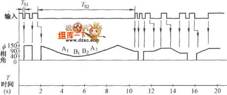
Infrared Remote Control Dimmer Light Circuit is shown below:
(View)
View full Circuit Diagram | Comments | Reading(734)
The motor vehicle headlight auto-dimming controller 9
Published:2011/4/19 21:54:00 Author:Ecco | Keyword: motor vehicle , headlight, auto-dimming , controller

The working principle.The vehicle headlight auto-dimming controller circuit consists of phototransistor Vl, transistors V2 and V3, resistor Rl-R5, capacitor C, diode VD and relay K, the circuit is shown as the figure 7-9.
S is headlamp switch of car, EL2 is the internallow beam light of headlamp, ELlis the high beam. V2 and V3forms a Schmitt trigger circuit.
When driving at night, turning on S, + l2V voltage is added to the high beam by the normally closed contact of S and K, so that the EL2 islit.
When meeting other cars, the light exposure from the opposite traveling car will make the conduction ability of V1and V2 increase, V3 turns on, K gets power and pulls in, the normally open contact isconnected, high beam ELl turns off,low beamEL2 turns on.
After meeting cars, the internal resistance of V1 will increaseas it has no light exposure,the conduction ability of V2 decreases, V3 is cut off, K releases, the normally closed contact is connected, normally open contact is disconnected, ELl turns on,low beamEL2 turns off.
C is a positive feedback circuit, which makes Schmitt trigger circuit delay.
R1-R5 choose 1/4W metal film resistors or carbon film resistors.
C chooses monolithic capacitors or polyester capacitor.
VD uses lN4007 silicon rectifier diode.
K selects a l2V 4098 DC relay.
(View)
View full Circuit Diagram | Comments | Reading(1370)
The motor vehicle headlight auto-dimming controller
Published:2011/4/19 21:04:00 Author:Ecco | Keyword: motor vehicle, headlight , auto-dimming , controller

The working principle.
The vehicle headlight auto-dimming controller circuit consists of photoresistor RG, potentiometer Rp, transistor V, diode VD and relay K, the circuit is shown as the figure 7-8.
When driving at night, turning on the headlamp switch S, RG is in the high impedance state when no light exposure, V cuts off, K isin releasing state, the normally closed contact Kl is connected, the normally open contact K2 is off, the internal high beam ELl of headlamp is lit, low beam EL2 is off.
When meeting other cars at night, the internal resistance of RC will decrease as the light exposure from the opposite traveling car, V will be saturated and conducted, K gets power and pulls in, the normally closed contact is disconnected, normally open contact is connected, the high beam ELl turns off, the low beam EHL2 turns on, that realizes the auto-dimming control. After meeting other cars, RG is in high impedance state, V cuts off, K releases, and the headlight automatically restores the upper light state.
RG usesMG45 seriesphotosensitive resistor.
RP uses small multi-turn potentiometers or variable resistor with carbon film synthesis.
VD uses lN4007 silicon rectifier diode.
V uses S8550 PNP transistors.
K selects a l2V JRX-l3F or JQX-4 DC relay.
(View)
View full Circuit Diagram | Comments | Reading(1543)
The motor vehicle headlight auto-dimming controller 7
Published:2011/4/19 21:23:00 Author:Ecco | Keyword: motor vehicle, headlight , auto-dimming , controller
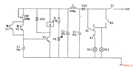
The motor vehicle headlight auto-dimming controller described in the example can automatically change the high beam into low beam at night, it does not need the driver to change the light by hand, and improve thesafety of driving at night.The working principle.The vehicle headlight auto-dimming controller circuit consists of power supply filter circuit and the light control circuit, the circuit is shown as the figure 7-7.
The power supply filter circuit is composed of isolation diode VD2, filter capacitor C2 and C3, inductor L, current limiting resistor R and light-emitting diode VL.
Light control circuit consists of photosensitive transistors Vl and V2, diodes VDl, potentiometer RP, capacitor Cl, transistors V3 and the relay K.
When driving at night, the power switch S1 is connected, +12 V voltage isprovided for control circuit afterfiltering. Light control switch S2 will be set to 1 (high beam) position, the high beam light ELl is lit,low beam EL2 is not lit.
R chooses 1/4W metal film resistor or carbon film resistors.
RP selects a small variable resistor or organic solid potentiometer.
Cl-C3 selects an electrolytic capacitor with thevoltagein 16V.
L selects a core fixed inductor with the current greater than 500mA.
K selects a l2V4098 DC relay. (View)
View full Circuit Diagram | Comments | Reading(602)
The motor vehicle headlight auto-dimming controller 6
Published:2011/4/19 21:38:00 Author:Ecco | Keyword: motor vehicle , headlight, auto-dimming , controller

The motor vehicle headlight auto-dimming controller described in the example can work alternately between the state of 1·9S high beam and low beam when driving at night. It will automatically become low beam when meeting other cars, it has a better dimming effect.
he working principle.The vehicle headlight auto-dimming controller circuit consists of voltage regulator, light control amplifier, and controlling implementation of the multivibrator circuit, the circuit is shown as the figure 7-6.
The voltage regulator circuit consists of three-terminal voltage regulator integrated circuit IC4, diode VD2 and filter capacitor C2.
The light control amplifier is composed of photocell GB, operational amplifier integrated circuit ICl (Nl-N4), IC2 (N5), resistors Rl-R8 and potentiometer RPl, RP2.
The multivibrator circuit is composed of time-base integrated circuit IC3, resistors R9, RlO, capacitors Cl, C3.
The controlling implementation is composed of resistors Rll, the transistor V, Relay K and diode VD3.
Rl-Rll choose 1/4W metal film resistor or carbon film resistors.
RP1 and RP2 choose sealed membrane variable resistors.
K selects a l2V JRX-l3F DC relay.
Gb selects small-capacity silicon photovoltaic cell.
(View)
View full Circuit Diagram | Comments | Reading(1324)
Gain 1~8000 times programmable amplifier circuit with PGA203
Published:2011/4/19 22:16:00 Author:Jessie | Keyword: Gain 1~8000 times, programmable, amplifier
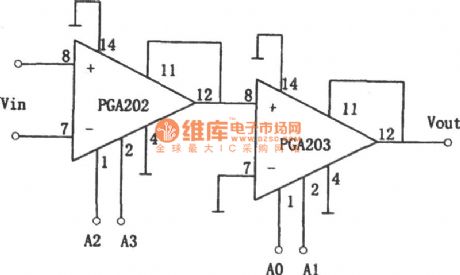
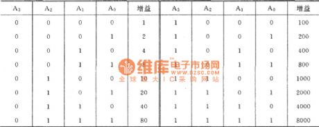
As shown is gain 1~8000 times programmable amplifier circuit. This circuit uses PGA202, PGA203 integrated chips. TheNC gain range of PGA202 is 1, 10, 100 and 1000. And theNC gain range of PGA203 is 1, 2,4 and 8.The corresponding relation of gain control terminals A2 (pin 1), A3 (pins 2) and the gain is listed in table below. (View)
View full Circuit Diagram | Comments | Reading(613)
Precision bridge isolated amplifier circuit with ISO101
Published:2011/4/18 21:39:00 Author:Jessie | Keyword: bridge isolated amplifier
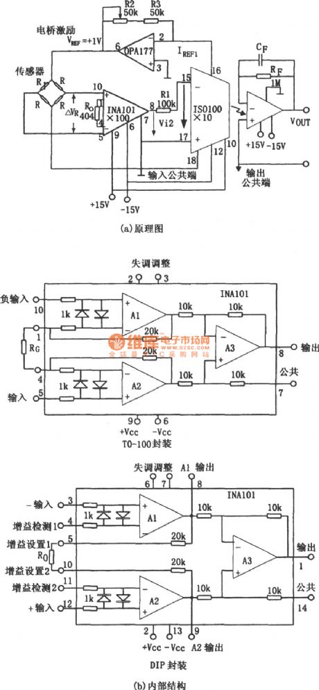
As shown in figureis precision bridge isolated amplifier circuit. Bridge circuit is widely used in automatic control, test, and data acquisition system. Figure (a) is a kind of high precision and high gain bridge isolated amplifier circuit. The sensor Rin bridge can be heat-sensitive, photosensitive or thermistor, etc. The signal voltage of sampling bridgeis single polarity signal, its value is 0~-10mV. This input signal firstamplifiered byhigh precision instrument INA101, and the voltage amplifier multiples of this amplifier is 100. INA101's internal circuit diagrams are as shown in figure (b), (c). (View)
View full Circuit Diagram | Comments | Reading(634)
Delay lamp controller circuit composed of CD4017
Published:2011/3/24 21:47:00 Author:may | Keyword: Delay lamp controller

Delay lamp controller circuit composed of CD4017 is shown in the following diagram:
(View)
View full Circuit Diagram | Comments | Reading(613)
800W three-terminal bidirectional thyristor dimmer circuit
Published:2011/4/5 20:44:00 Author:may | Keyword: 800W, three-terminal, bidirectional thyristor, dimmer
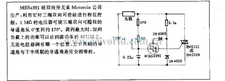
MBS4991 silicon bilateral switch is produced by Motorala company. We can utilize it to control phase of three-terminal bidirectional thyristor. 1MΩ regulation resistance can let the turn-on angle of three-terminal bidirectional thyristor changing from 0° to about 170°. When adjusting to maximum, the power added to load can reach 97% of full power. Now matter what the posistion the regulation resistance is, turn-on angle of upper half period and the turn-on angle of lower half poriod is exatly equal.
(View)
View full Circuit Diagram | Comments | Reading(1070)
Operation amplifier low-pass filter circuit
Published:2011/4/17 21:08:00 Author:Jessie | Keyword: Operation amplifier low-pass filter
View full Circuit Diagram | Comments | Reading(645)
Operation amplifier venturi filter circuit diagram
Published:2011/4/13 20:18:00 Author:Jessie | Keyword: Operation amplifier, venturi filter
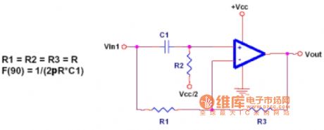
For all frequencies venturi filters are the same gain, but it can change the angle of signals, it also can be used for angle correction circuit at the same time. Circuit has a 90 degrees' phase shift on the signal frequency F,a0 degree's phaseshifton dc, and a 180 degrees' phase shifton the high frequency. (View)
View full Circuit Diagram | Comments | Reading(699)
4~20mA Isolation analog (ISO100) circuit
Published:2011/4/18 4:27:00 Author:Jessie | Keyword: Isolation analog
View full Circuit Diagram | Comments | Reading(722)
| Pages:4/5 12345 |
Circuit Categories
power supply circuit
Amplifier Circuit
Basic Circuit
LED and Light Circuit
Sensor Circuit
Signal Processing
Electrical Equipment Circuit
Control Circuit
Remote Control Circuit
A/D-D/A Converter Circuit
Audio Circuit
Measuring and Test Circuit
Communication Circuit
Computer-Related Circuit
555 Circuit
Automotive Circuit
Repairing Circuit


