
Index 388
Photosensitive diode principle circuit
Published:2011/7/3 21:49:00 Author:Christina | Keyword: Photosensitive diode, principle circuit
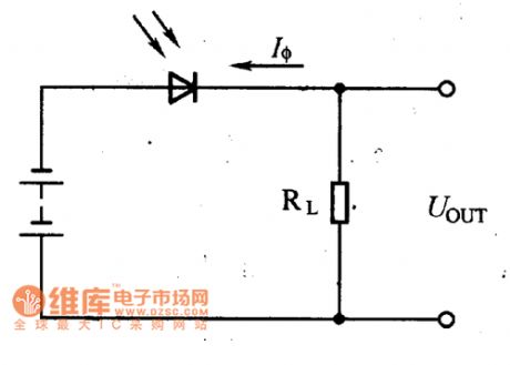
The photosensitive diode is the same as the ordinary photosensitive diode, the PN junction of it has the one-way conductivity, so we need to add the inverse voltage when the photosensitive diode is working, as the figure shows. When there is no illumination, the circuit also has the small reverse saturated leakage current, this is equivalent of the conduction of the photosensitive diode; when there is the illumination, the PN junction is bombarded by the photons, the valence electrons which are bounded absorb the photon energy to produce the electron. The number of these current carriers has little effect for the most of carriers.
Figure:Photosensitive diode principle circuit (View)
View full Circuit Diagram | Comments | Reading(1468)
Electric welding machine no load electricity saver 10
Published:2011/6/30 21:38:00 Author:Nicole | Keyword: electric welding machine, electricity saver

The electric welding machine no load electricity saver circuit is composed of detection circuit and energy saving control circuit, it is shown in the figuer 8-14.
The detection circuit is made of current transformer TA, diodes VD1, VD2, transistor V, bridge rectifiers UR, filter capacitor C3.
The energy saving control circuit consists of resistors R1, R2, capacitors C1, C2, steady voltage diodes VS1, VS2, thyristor VT, diode VD3, relay K and AC contactor KM.
The electric welding machine transformer is composed of knife switch Q, fuse F.
(View)
View full Circuit Diagram | Comments | Reading(3311)
Electric welding machine no load electricity saver 8
Published:2011/6/30 21:30:00 Author:Nicole | Keyword: electric welding machine, electricity saver
The electric welding machine no load electricity saver circuit is composed of knife switch Q, relays K1, K2, intermediate relay KA, AC contactor KM, time relay KT, reed switch SA, diodes VD1, VD2, indication light HL, resistor R, capacitors C1-C3, potentiometers RP1, RP2 and electric welding machine transformer T, it is shown in the figure 8-12.
When KM pulls in, but it is not welded, the induced voltage which produced by the both sides of T's secondary winding is rectified by VD2 and then it is added to K2, K2 is pulled in, K2's normally open contact is turned on, KT pulls in and it starts to timing.
(View)
View full Circuit Diagram | Comments | Reading(2111)
Electric welding machine no load electricity saver 7
Published:2011/6/30 21:10:00 Author:Nicole | Keyword: electric welding machine, electricity saver

The electric welding machine no load electricity saver circuit is composed of control power transformer T1, intermediate relay KA, relay KT, AC contactor KM, potentiometer RP and indication light HL1, HL2, it is shown in the figure 8-11.
After knife switch Q is turned on, T1 works, power indication light HL1 lights. When welding, below, intermediate relays KA pull in, the normally open contact KA1, KA2 are turned on, then KKM's normally open contact KM1, KM2 are turned on, the normally closed contact KM3 and KM4 are cut off, it works, it shows it can do welding.
(View)
View full Circuit Diagram | Comments | Reading(1508)
Electric welding machine no load electricity saver 6
Published:2011/6/30 21:00:00 Author:Nicole | Keyword: electric welding machine, electricity saver
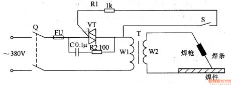
The electric welding machine no load electricity saver circuit is composed of knife switch Q, fuse FU, capacitor C, resistors R1, R2, thyristor VT, electric welding machine transformer T and trigger switch S, it is shown in the figure 8-10.
When knife switch Q is turned on, 380V AC voltage is added to T's circuit by Q(the circuit is made of FU, VT, C, R2 and winding W1). When trigger switch S is not turned on, VT is in off state, C, R2 are connected into the circuit, then the electric welding machine is in electricity saving state, the current which flows T's loop is smaller.
(View)
View full Circuit Diagram | Comments | Reading(3573)
Electric welding machine no load electricity saver 5
Published:2011/6/30 20:52:00 Author:Nicole | Keyword: electric welding machine, electricity saver

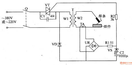
The electric welding machine no load electricity saver circuit is composed of current detection control circuit and electricity saving control circuit, it is shown in the figure 8-9.
The current detection control circuit is made of current transformer TA, bridge rectifiers UR, resistor R1, steady voltage diode VS, capacitor C2 and diode VD.
When the welding rod needs to change or stop transitorily for some reasons, C2 discharges to VT's gate passes through VS and R2, then VT keeps on. After C2 finishes discharging, VT is off, C1 is connected into another loop of T, the electric welding machine is in saving state again.
(View)
View full Circuit Diagram | Comments | Reading(3411)
Electric welding machine no load electricity saver 4
Published:2011/6/30 20:40:00 Author:Nicole | Keyword: electric welding machine, electricity saver

The electric welding machine no load electricity saver circuit is composed of +12V power supply circuit, current detection control circuit, dalay control circuit and control implement circuit, it is shown in the figure 8-8.
The +12V power supply circuit is made of knife switch Q, fuse FU, power transformer T1, bridge rectifiers UR and filter capacitor C2.
The dalay control circuit consists of resistor R7, capacitors C3, C4, time base integrated circuit IC, relay K, AC contactor KM and diode VD5.
T2 is electric welding machine transformer, the energy saving circuit is composed of R1, R8, C1.
(View)
View full Circuit Diagram | Comments | Reading(4577)
2CU silicon photosensitive diode appearance circuit
Published:2011/7/3 21:18:00 Author:Christina | Keyword: silicon, photosensitive diode, appearance circuit
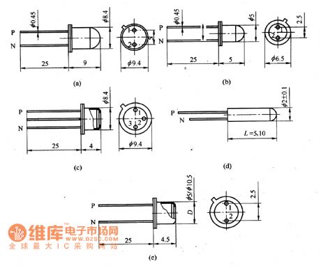
The 2CU silicon photosensitive diode is in the sealed shell package, there is the optical lens or flat glass window on the top of the package. The 2CU silicon photosensitive diode can be used to receive the light and also can be used in the photo-electric conversion automatic control instrument, the trigger, the photoelectric coupler, the encoder and decoder, the characteristics identification circuit, the process control circuit and the laser receiving circuit.
The 2CU101/201 silicon photosensitive diode can be used to receive the light signal of the fibre-optical communication. The appearance structure is as shown in the figure.
2CU silicon photosensitive diode appearance circuit (View)
View full Circuit Diagram | Comments | Reading(555)
A45L9332F dynamic memory integrated circuit
Published:2011/7/3 21:32:00 Author:Christina | Keyword: dynamic memory, integrated circuit
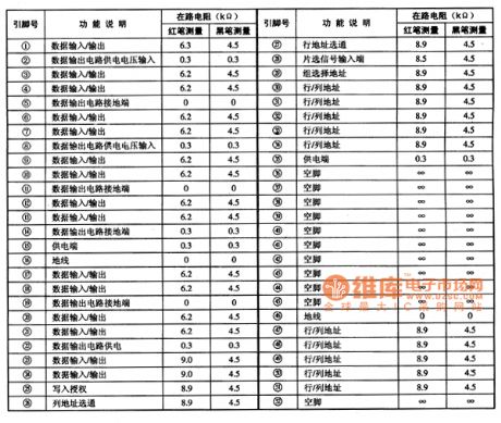
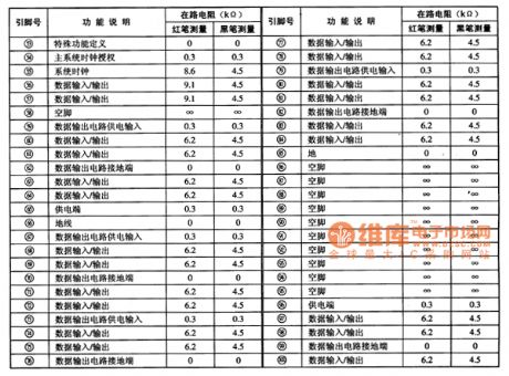
The A45L9332F is designed as one kind of 16777216-bit synchronous high data rate dynamic memory integrated circuit that can be used in the ChangHong HP series rear projection color TVs.
1.Features
The A45L9332FF uses the CMOS technology, and it is accurately controlled by the system clock to finish the storage work of data. The internal storage space is divided into two groups, every group is 256Kx32bit. This ciruit has the system clock circuit, the data input/output interface circuit, the line & row address selective passing circuit, the line & row address unit, the data circuit power supply system and other subsidiary function circuits.
2.Pin functions and data
The A45L933FF uses the 100-pin square flat package structure, the pin functions and data is as shown in table 1.
Table 1 The pin functions and data of the A45L9332F
(View)
View full Circuit Diagram | Comments | Reading(476)
2DU photosensitive diode application circuit
Published:2011/7/3 21:36:00 Author:Christina | Keyword: photosensitive diode, application circuit
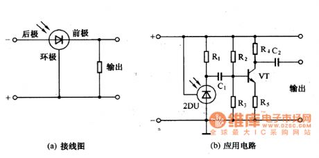
The 2DU photosensitive diode application circuit has three pins: the front pole, the rear pole and the circumpolar. The connection modes and the application circuits are as shown in the figure.
Figure: 2DU photosensitive diode application circuit (View)
View full Circuit Diagram | Comments | Reading(666)
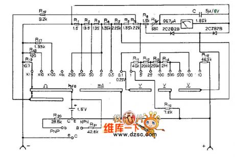
MF88 multimeter circuit diagram
Published:2011/6/24 4:40:00 Author:Nicole | Keyword: multimeter
View full Circuit Diagram | Comments | Reading(755)
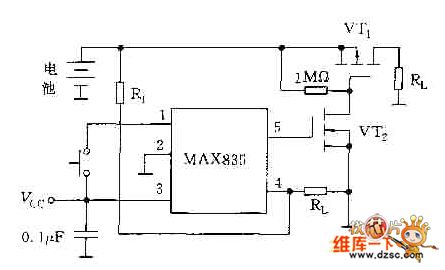
Monitoring battery low voltage turning off power supply circuit diagram
Published:2011/6/24 8:29:00 Author:Nicole | Keyword: Monitoring, battery, low voltage, power supply
View full Circuit Diagram | Comments | Reading(503)
TA8152AFN TV/FM radio integrated circuit
Published:2011/7/1 1:04:00 Author:chopper | Keyword: TV/FM, radio, integrated circuit
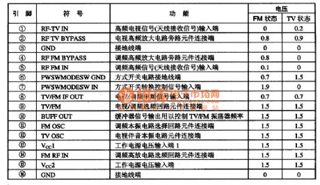
TA8152AFN is a FN/FM radio integrated circuit produced by Company TOSHIBA,and it is applied to the sound system,computer sound system.TA8152AFN adopts dual inline 16 pinned package.And its function and data of pins of integrated circuit are shown as chart 1.
(View)
View full Circuit Diagram | Comments | Reading(584)
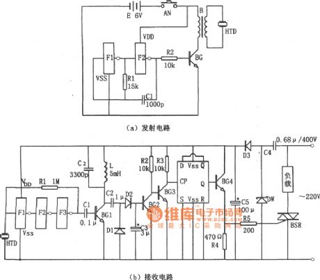
ultrasonic remote switch (C033) circuit
Published:2011/6/30 1:15:00 Author:chopper | Keyword: ultrasonic, remote switch
View full Circuit Diagram | Comments | Reading(385)
Double-tube Flyback DC-DC Converter Circuit
Published:2011/6/24 1:27:00 Author:Michel | Keyword: Double-tube, Flyback, DC-DC , Converter Circuit
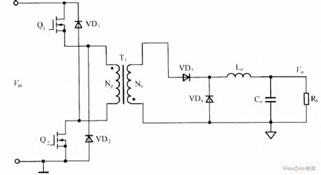
Double-tube flyback DC-DC converter circuit is shown as above.Among them,transformer,T1 acts as isolation,transmission,energy storge and 9 stores energy when switch tubes Q1 and Q2 turns on and Np releases energy to Ns,meanwhile,Np leakage feedbacks input signal via VD1 and VD2 and RCD leakage peak absorbing circuit can be saved when switch tubes Q1 and Q2 turns off.The low-pass filter composed of the inductor Lo and capacitance Co should be added to output port.In output loop,a rectifier diode VD3 is needed. (View)
View full Circuit Diagram | Comments | Reading(2236)
The Most Simple Capacitance Step-down Circuit
Published:2011/7/1 8:34:00 Author:Michel | Keyword: Most Simple, Capacitance Step-down, Circuit
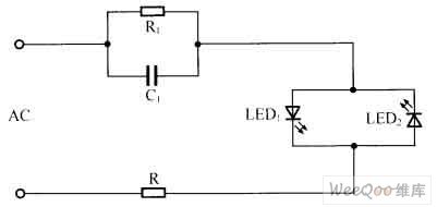
Shown as the picture,the two reverse parallel connection LED commute the step-down AC current.The circuit is widely used in luminous lamp, button lights and some position indicator light which have no high requirement.
Picture:The Most Simple Capacitance Step-down Circuit (View)
View full Circuit Diagram | Comments | Reading(600)
OPA604 High Performance and Small Power Audio Amplifier Circuit
Published:2011/6/24 13:21:00 Author:Michel | Keyword: High Performance, Small Power, Audio, Amplifier Circuit

The above picture is high performance and small power audio power amplifier circuit.This circuit's former level uses the mosfet hi-fi op-amp OPA604 and next level adopts high-speed buffer BUF634 and voltage series negative feedback is used between two levels amplifiers. This circuit voltage magnification depends on two resistances (5kΩ and 250Ω)of feedback branchs and its value is l+5kΩ/250Ω≈21 times.BUF634 is high-speed buffers and itsinternal structure simplified circuit is shown in figure (b). (View)
View full Circuit Diagram | Comments | Reading(1706)
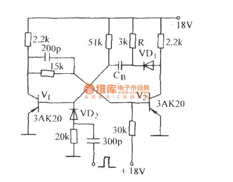
The high-speed single steay circuit (1)
Published:2011/7/2 4:29:00 Author:Borg | Keyword: high-speed, single steay circuit
View full Circuit Diagram | Comments | Reading(462)
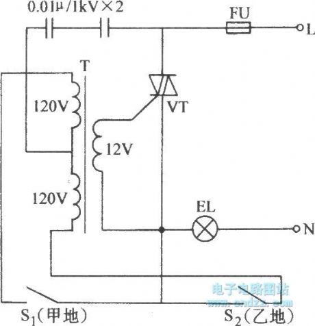
The electric ganged switch switch
Published:2011/7/2 23:41:00 Author:Borg | Keyword: electric, ganged switch
View full Circuit Diagram | Comments | Reading(514)
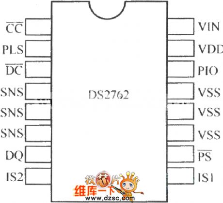
DS2762 pin arrangement circuit
Published:2011/7/1 1:28:00 Author:TaoXi | Keyword: pin arrangement
View full Circuit Diagram | Comments | Reading(447)
| Pages:388/471 At 20381382383384385386387388389390391392393394395396397398399400Under 20 |
Circuit Categories
power supply circuit
Amplifier Circuit
Basic Circuit
LED and Light Circuit
Sensor Circuit
Signal Processing
Electrical Equipment Circuit
Control Circuit
Remote Control Circuit
A/D-D/A Converter Circuit
Audio Circuit
Measuring and Test Circuit
Communication Circuit
Computer-Related Circuit
555 Circuit
Automotive Circuit
Repairing Circuit