
555 Circuit
Index 8
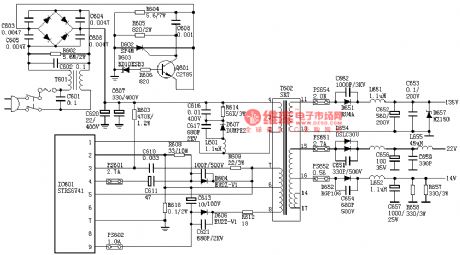
SONY G3F-K Power Supply Circuit-1
Published:2011/8/11 5:43:00 Author:Sue | Keyword: Power Supply

View full Circuit Diagram | Comments | Reading(1118)
SONY F29 Power Supply Circuit
Published:2011/8/11 5:41:00 Author:Sue | Keyword: Power Supply
View full Circuit Diagram | Comments | Reading(947)
Broadband Low Noise Amplifier Circuit
Published:2011/7/15 5:31:00 Author:Sue | Keyword: Broadband, Low Noise, Amplifier

As shown in the figure, it is the broadband low noise amplifier circuit. (View)
View full Circuit Diagram | Comments | Reading(1662)
Nissan A32-EL Power Supply Circuit (6)
Published:2011/7/15 5:23:00 Author:Sue | Keyword: Nissan, Power Supply

View full Circuit Diagram | Comments | Reading(824)
Comprehensive protector belt circuit composed of 555
Published:2011/8/22 22:09:00 Author:Rebekka | Keyword: Comprehensive protector belt, 555

Start upcircuit is composed of the start button QA, IC1 (555), IC2 (555), J1 and so on. When you press the QA, the +12 V voltage output by the buck rectifier circuit will be added to IC1, IC2, then relay J1 will be pulled. It also starts the bell ring. When it adds a +12 V voltage, the IC1 is set aspin potential of pin ② is low (the voltage on C1can not mutate), and C1 charges for R1, when the C1 charges to make IC1 ⑥ potential higher than 2 feet / 3VDD, IC1 will be reset. (View)
View full Circuit Diagram | Comments | Reading(945)
The regulator: DC-DC circuit, power supply monitor pin and its main features AD580
Published:2011/8/23 22:21:00 Author:Seven | Keyword: DC-DC circuit, power supply, monitor pin

AD580 reference voltage circuit (+2.5V) This is a wide band 3-terminal Vref circuit; its output voltage is 2.5V; the primary fault of AD580M output voltage is ±4%; the temperature drift of AD580U is lower than 10*10-6/⁰C; the long-term stability is 250μV; the input voltage range is 4.5~30V; the max input voltage is 40V; when the environment temperature is lower than 25⁰C, the power consumption is 350mW.
(View)
View full Circuit Diagram | Comments | Reading(903)
Dual-axis magnetic field sensor application circuit
Published:2011/8/11 4:51:00 Author:John | Keyword: Dual-axis magnetic field sensor, application circuit
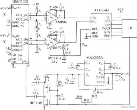
Dual-axis magnetic field sensor application circuit is shown. A two-axis magnetic sensor HMC1002 and two pieces of AMP04 (A1, A2) are used to simultaneously measure the magnetic field of X-axis direction and Y-axis direction. Dual-direction voltage signal output by HMC1002 can be respectively amplified by A1 and A2. And they are connected to the 12 bit A / D converter TLC2543 analog input and reference terminal. Then it is connected to μP through the interface circuit. MAX662A is the efficient DC / DC converter, which raises + 5 V power supply to 10 V power supply. The 10 V power supply can power the drive IRF7105. The input signal of the drive is from the μP.
(View)
View full Circuit Diagram | Comments | Reading(2566)
single-axis magnetic field sensor with serial interface circuit
Published:2011/8/11 4:41:00 Author:John | Keyword: single-axis magnetic field sensor, serial interface
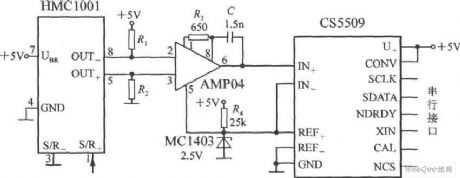
Single-axis magnetic field sensor with serial interface circuit is shown. The circuit's output stage uses a 16-bit A / D converter CS5509, which can be equipped with a microprocessor or microcontroller through the interface circuit. The output voltage (Uo) of the AMP04 is connected to the analog input of CS5509. MC1403-type band-gap reference voltage source powers CS5509 with 2.5V reference voltage.
(View)
View full Circuit Diagram | Comments | Reading(1507)
NISSAN new Teana audio (with navigation system) circuit(f)
Published:2011/7/28 4:12:00 Author:John | Keyword: navigation system, new Teana audio
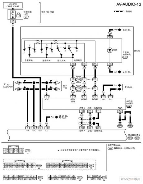
NISSAN new Teana audio (with navigation system) circuit(e) is shown.
(View)
View full Circuit Diagram | Comments | Reading(784)
555 water level control circuit diagram composed of 555 and music circuit
Published:2011/8/17 2:35:00 Author:Rebekka | Keyword: 555 , water level control , music circuit
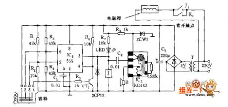
1, 2, 3, 4 are four probes. When the surface declines and pin 3 exposes, the pin2 of IC1 is a low level(<1/3 VDD). 555 sets, J pull-in, solenoid valve starts to work and water injects to container. At the same time, IC2 is triggered and play a song to inform you it is going to inject water. When the water resistance between 1 and 2 makes the potential of pin6 rises higher than 2/3VDD and trigger the level, 555 resets, pin 3 turns to low level. J releases, the solenoid valve power turns off. Probe 4 is insurance probe, when the surface of water rises to probe 4 because of any reasons, VT1 will be conducted and turned to a low level, it forces 555 resetting and turning off the solenoid valve. (View)
View full Circuit Diagram | Comments | Reading(2650)
The water level control circuit diagram composed of reduction voltage rectification circuit and 555
Published:2011/8/17 3:16:00 Author:Rebekka | Keyword: water level control , reduction voltage rectification , 555
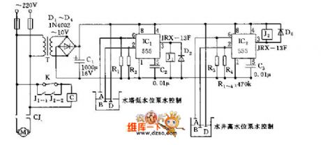
To achieve the automatic control of water tower and water level,probes B and D are put in well. Under normal circumstances, it should be in a certain depth of water level. It makes the output terminal 3 of IC2(555) circuit turn to low level, J2 pull-in, J2-2 closed. Pumping continuously makes polar B and polar D expose from water, pin 2 turn to a low level. It makes IC2 turn-over position, pin3 turn to a high level, J2 release, J2-2 disconnect to avoid motor from idle running, then it willmonitor the water level of the well. (View)
View full Circuit Diagram | Comments | Reading(3138)
Mitsubishi Pajero light off-road vehicle automobile instrument wiring(with electroniccompass) circuit diagram
Published:2011/8/12 4:34:00 Author:Rebekka | Keyword: Mitsubishi Pajero, light off-road vehicle, automobile instrument wiring , electroniccompass
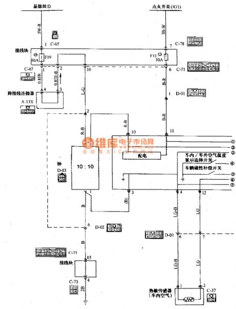
Mitsubishi Pajero light off-road vehicle meter(mounted electronic compass vehicle)wiring circuit diagram is shown as above.
(View)
View full Circuit Diagram | Comments | Reading(2248)
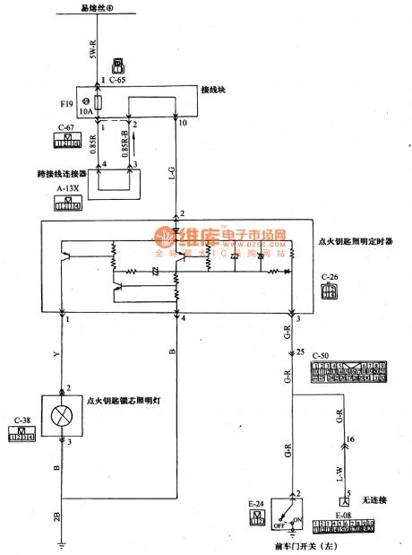
Mitsubishi Pajero light off-road vehicle ignition key core and floodlight wiring circuit diagram
Published:2011/8/12 4:32:00 Author:Rebekka | Keyword: Mitsubishi Pajero, light off-road vehicle , ignition key core , floodlight wiring
View full Circuit Diagram | Comments | Reading(2294)
The NISSAN new Teana gear-shifting electromagnetic valve B circut
Published:2011/8/11 7:41:00 Author:Borg | Keyword: NISSAN, Teana, gear-shifting, electromagnetic valve

The NISSAN new Teana gear-shifting electromagnetic valve B circut (View)
View full Circuit Diagram | Comments | Reading(933)
The NISSAN new Teana fluid torque clutch magnetic valve circut
Published:2011/8/11 7:59:00 Author:Borg | Keyword: NISSAN, Teana, fluid torque clutch, magnetic valve

The NISSAN new Teana fluid torque clutch magnetic valve circut (View)
View full Circuit Diagram | Comments | Reading(790)
The NISSAN new Teana exceeding clutch magnetic valve circut
Published:2011/8/11 8:01:00 Author:Borg | Keyword: NISSAN, Teana, magnetic valve
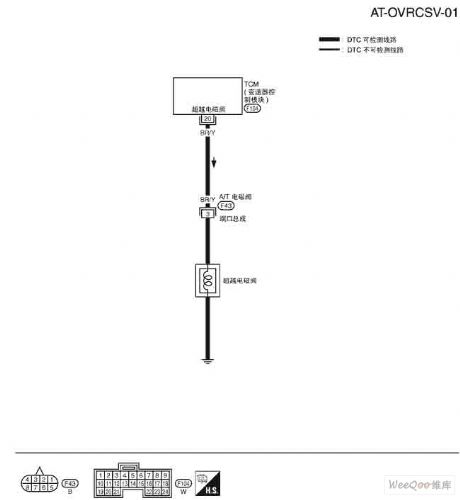
The NISSAN new Teana exceeding clutch magnetic valve circut (View)
View full Circuit Diagram | Comments | Reading(862)
The NISSAN new Teana A/T temperature sensor circuit and TCM power supply circut
Published:2011/8/11 8:03:00 Author:Borg | Keyword: NISSAN, Teana, temperature sensor, TCM, power supply
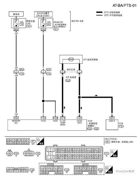
The NISSAN new Teana A/T temperature sensor circuit and TCM power supply circut (View)
View full Circuit Diagram | Comments | Reading(1321)
The NISSAN new Teana engine speed signal circut
Published:2011/8/11 8:04:00 Author:Borg | Keyword: NISSAN, Teana, engine speed
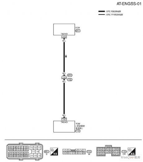
The NISSAN new Teana engine speed signal circut (View)
View full Circuit Diagram | Comments | Reading(848)
The NISSAN new Teana turbine rotating speed sensor circut
Published:2011/8/11 8:06:00 Author:Borg | Keyword: NISSAN, Teana, rotating speed sensor, turbine
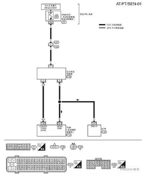
The NISSAN new Teana turbine rotating speed sensor circut (View)
View full Circuit Diagram | Comments | Reading(956)
The NISSAN new Teana stereo (with GPS) circuit (3)
Published:2011/8/11 7:23:00 Author:Borg | Keyword: NISSAN, Teana, stereo
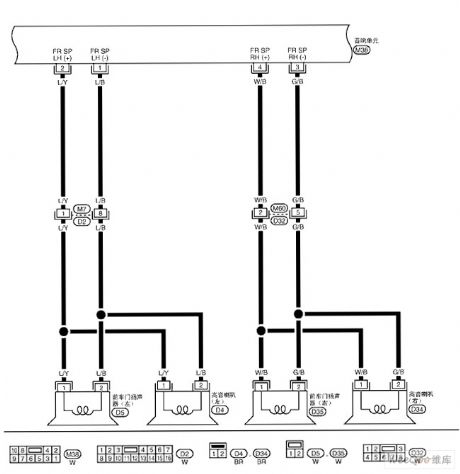
The NISSAN new Teana stereo (with GPS) circuit (3) (View)
View full Circuit Diagram | Comments | Reading(864)
| Pages:8/47 1234567891011121314151617181920Under 20 |
Circuit Categories
power supply circuit
Amplifier Circuit
Basic Circuit
LED and Light Circuit
Sensor Circuit
Signal Processing
Electrical Equipment Circuit
Control Circuit
Remote Control Circuit
A/D-D/A Converter Circuit
Audio Circuit
Measuring and Test Circuit
Communication Circuit
Computer-Related Circuit
555 Circuit
Automotive Circuit
Repairing Circuit