
555 Circuit
Index 7
555 Dual astable multivibrator circuit
Published:2011/9/18 21:46:00 Author:Ecco | Keyword: 555, Dual , astable , multivibrator
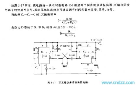
As shown in Figure 3-17, the circuit has two synchronized multivibrators whichare composed of 556 dual time-base circuit, andit can output two clock pulse signals simultaneously, the spacing and oscillation frequency can be changed by adjusting the time constant. When you select C1 = C2 = C, f = 0.91 / (R1 + R2) C, duty cycle depends on the value of R1 and R2 and it can be up to 5% to 95%.
(View)
View full Circuit Diagram | Comments | Reading(2266)
Audi Cruise Control circuit
Published:2011/9/14 21:02:00 Author:John | Keyword: Cruise Control

View full Circuit Diagram | Comments | Reading(1315)
Toy model sign indication circuit
Published:2011/9/12 21:17:00 Author:John | Keyword: Toy model sign indication


The circuit is generally set in a variety of junctions or corners, aiming to indicate the direction for the toy train or car. The main direction is to rely on its successive group of light-emitting diodes, as shown.
IC14017 is the decimal count splitter, which has five output named Q0~Q4 while only 4 is used to form the quaternary count distributor. N1~N5 are 5 Schmitt triggers. N1 is the oscillator to provide IC1’s clock source. N2 ~ N5 5 are 4 monostable triggers. T1~T4 are the drive circuit for light-emitting diode.
(View)
View full Circuit Diagram | Comments | Reading(989)
NISSAN new Teana audio (with navigation system) circuit(e)
Published:2011/9/12 22:00:00 Author:John | Keyword: navigation system, new Teana audio
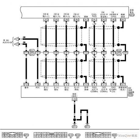
NISSAN new Teana audio (with navigation system) circuit is shown.
(View)
View full Circuit Diagram | Comments | Reading(849)
Nokia 7xxx Mobile Schematic Diagram 07
Published:2011/9/4 7:31:00 Author:Joyce | Keyword: Mobile, Schematic
View full Circuit Diagram | Comments | Reading(3312)
Economical Fluorescence Display Circuit Composed of 555
Published:2011/9/4 7:31:00 Author:Joyce | Keyword: Economical, Fluorescence , Display

As shown in the figure is an economical fluorescence display circuit. The core of the circuit is a multivibrator composed of 555 ,R1, R2,and C1 ect, whose oscillation frequency is: f = 1.44 / (R1 + 2 R2)C1, the frequency of the corresponding parameters in the figure above being about 4 kHz. DC bias of the filament in the figure is : VDD ·R4/ (R3 + R4) ≈ 6 V. Adding a dc voltage of 6 V and an nkHz ac voltage whose Vp-p voltage is about 4 V to the filament of the fluorescent character-display tube on the calculator would make the fluorescent character display tube display. The structure of the circuit is simple thus it is easy to make. (View)
View full Circuit Diagram | Comments | Reading(1013)
Tremolo amplifier circuit
Published:2011/9/9 2:24:00 Author:John | Keyword: Tremolo amplifier

The amplifier utilizes undersonic frequency (usually 5 ~ 15Hz) to do amplitude modulation for the audio input signal. The used National's LM389 IC contains three transistors and a power amplifier in the internal array. These transistors constitute the differential pair and active current source tail end. The differential amplifier output is proportional with two input signals’ product. Gain control potentiometer is used to adjust the desired tremolo intensity. R, C network within levels constitute the 160Hz high-pass filter and the tremolo frequency is required below 160Hz.
(View)
View full Circuit Diagram | Comments | Reading(1771)
VG095 FOG
Published:2011/9/9 3:30:00 Author:John | Keyword: Fiber Optic Gyro, Gyro, FOG, angular velocity sensor, VG gyro, gyro Russia

Fiber optic gyroscope VG095M is a micro-precision sensor, which is based on VG941-3AM. It improves bias value and scale factor stability. And it responses the angular rate of moving objects in the form of the voltage. The symbols of the output voltage depend on the rotating direction around the sensitive axis.
weight
80 gram
size
25 x 35 x60mm
power consumption
1 Watt
bias stability
15 deg/h
proportionality factor
10 mV/deg/s
Scale factor stability
0.1 %
random walk
0.1 deg/ sqrt h
measuring range
300 deg/s
bandwidth
0...450 Hz
working temperature
-30°C ... +70°C
Storage temperature
- 55°C … +85°C
vibration
6 g (RMS), 20Hz... 2000Hz
attack
90 g, 1 ms (View)
View full Circuit Diagram | Comments | Reading(1041)
555 Water level-controlled Circuit
Published:2011/9/3 10:40:00 Author:Zoey | Keyword: Water level-controlled
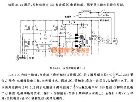
As shown in the picture 24-24, the controlling circuit is composed of 555 and a music IC circuit. This circuit is used to control the conductive liquid.
1,2,3, and 4 refer to four pins. When the liquid level goes down and Pin 3 is exposed, Pin 2 of IC1will bein low level(<1/3VDD), 555 will set and J will close, and solenoid valve will get electrical power and begin to work and infuse water to the container. Meanwhile, IC2 will be triggered and play music to inform people to infuse water. When water levelreachespin 2, water resistance between pin 1 and pin 2 will make the level of pin 6 higher than 2/3VDD, then 555 will reset, pin 3 will be in low level, J willrelease, and solenoid valve will cut off electric power and water supply. Pin 4 is an insurance needle, when water level reaches pin 4, VT1 will conduct and be in low level, forcing 555 to reset and cut off the solenoid valve. (View)
View full Circuit Diagram | Comments | Reading(1313)
Circuit of a 555 Multi-vibrator with a changeable tone
Published:2011/9/3 10:38:00 Author:Zoey | Keyword: 555 Multi-vibrator, a changeable tone
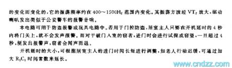
This transposition circuit is composed of two time-based 555 circuit, it can emit continuous oscillation wave that ranges from 400~2500 Hz, similar to the sound of police wagon.
This circuit consists of time-lapse oscillator, low-frequency oscillator and modem audio generator; the circuit can be seen in the picture3-21.
The gating switch HG is magnet-controlled and it remains open usually. When IC1 ceases to be reposited and starts to oscillate, the oscillation frequency is
fc=1.44/(R2+2R3)C2
The charge and discharge time of C2 is 3.94s and 0.06s respectively. Output wave of C2 is sawtooth voltage wave, which controls the oscillation frequency conversely.
The multi-vibrator is composed of IC2,R4, R5 and C3, with its frequency can be changed. Its basic oscillation frequency is about 1000Hz, and its actual oscillation frequency changes as sawtooth voltage wave change. The oscillation square wave will be magnified through VT2, and then drive the speaker to make an alarm that sounds like the police wagon.
The circuit can be used in burglarproof system and circuit of various toys, the prolonged time of start-up can be adjusted according to the time takes for housemasters to enter the house. For example, it takes longer time for old people to enter the house, so we can prolong the time by enlarging the time constant of R1C1. (View)
View full Circuit Diagram | Comments | Reading(1441)
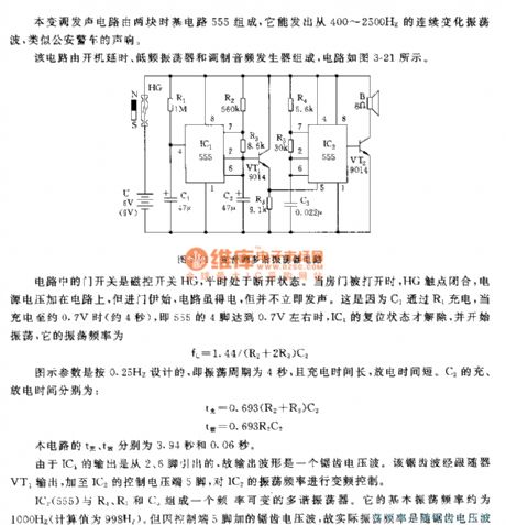
The regulator: DC-DC circuit, power supply monitor pin and its main features LM105
Published:2011/8/28 1:16:00 Author:Seven | Keyword: DC-DC circuit, power supply, monitor pin
LM105/205/305/305A/376--the adjustable stabilizer (positive output)This a positive output stabilizer whose output voltage is adjustable; the output voltage range is 4.5~40V; the output current is 45mA; the wave impedance ratio is 0.01%/V; the max voltage of LM105/205/305A is 50V, the max voltage of LM305/376 is 40V, the power consumption of LM376 is 400mW, the rest is 800mW; the working temperature is LM105 is -55~+125℃; the working temperature is LM205 is -25~+85℃, that of LM305/305A/376 is 0~75℃.
(View)
View full Circuit Diagram | Comments | Reading(1205)
Nokia 7xxx Mobile Schematic Diagram 03
Published:2011/8/12 3:10:00 Author:Joyce | Keyword: Mobile , Schematic
Nokia 7xxx Mobile Schematic Diagram 03 (View)
View full Circuit Diagram | Comments | Reading(2033)
Over-voltage Instruction Circuit Composed of 555
Published:2011/8/12 3:03:00 Author:Joyce | Keyword: Over-voltage , Instruction, 555
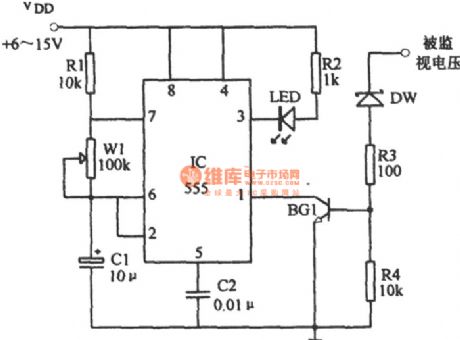
As shown in the figure is an over-voltage instruction circuit, which is composed of multivibrator, detection circuit, and LED (light-emitting diode) etc. The multivibrator constitutes of 555, R1, W1 and C1 ect, and it is connected with the collector of the triode and grounding feet 1 of 555. When the monitored voltage exceeds the set value ,the stabilivolt DW will be punctured to break over detector tube BG1.The multivibrator starts oscillation for the connection of power circuit, and the oscillation signal output will drive the LED to flash. Breakdown voltage of stabilivolt DW and the resistance of current limiting resistance R3 can be chosen according to the voltage to be monitored. (View)
View full Circuit Diagram | Comments | Reading(1003)
Nokia 7xxx Mobile Schematic Diagram 06
Published:2011/8/12 3:08:00 Author:Joyce | Keyword: Mobile , Schematic
Nokia 7xxx Mobile Schematic Diagram 06 (View)
View full Circuit Diagram | Comments | Reading(3904)
Nokia 7xxx Mobile Schematic Diagram 05
Published:2011/8/12 3:07:00 Author:Joyce | Keyword: Mobile , Schematic

Nokia 7xxx Mobile Schematic Diagram 05 (View)
View full Circuit Diagram | Comments | Reading(1125)
Nokia 7xxx Mobile Schematic Diagram 04
Published:2011/8/12 3:09:00 Author:Joyce | Keyword: Mobile , Schematic
Nokia 7xxx Mobile Schematic Diagram 04 (View)
View full Circuit Diagram | Comments | Reading(1934)
Nokia 7xxx Mobile Schematic Diagram 02
Published:2011/8/12 3:11:00 Author:Joyce | Keyword: Mobile, Schematic

Nokia 7xxx Mobile Schematic Diagram 02 (View)
View full Circuit Diagram | Comments | Reading(1193)
Nokia 7xxx Mobile Schematic Diagram 01
Published:2011/8/12 3:13:00 Author:Joyce | Keyword: Mobile , Schematic

Nokia 7xxx Mobile Schematic Diagram 01 (View)
View full Circuit Diagram | Comments | Reading(2020)
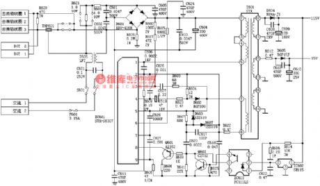
SONY KV2184 Power Supply Circuit
Published:2011/8/11 5:46:00 Author:Sue | Keyword: Power Supply

View full Circuit Diagram | Comments | Reading(1519)
SONY KV2185 Power Supply Circuit
Published:2011/8/11 5:46:00 Author:Sue | Keyword: Power Supply
View full Circuit Diagram | Comments | Reading(1569)
| Pages:7/47 1234567891011121314151617181920Under 20 |
Circuit Categories
power supply circuit
Amplifier Circuit
Basic Circuit
LED and Light Circuit
Sensor Circuit
Signal Processing
Electrical Equipment Circuit
Control Circuit
Remote Control Circuit
A/D-D/A Converter Circuit
Audio Circuit
Measuring and Test Circuit
Communication Circuit
Computer-Related Circuit
555 Circuit
Automotive Circuit
Repairing Circuit