555 Circuit
Index 15
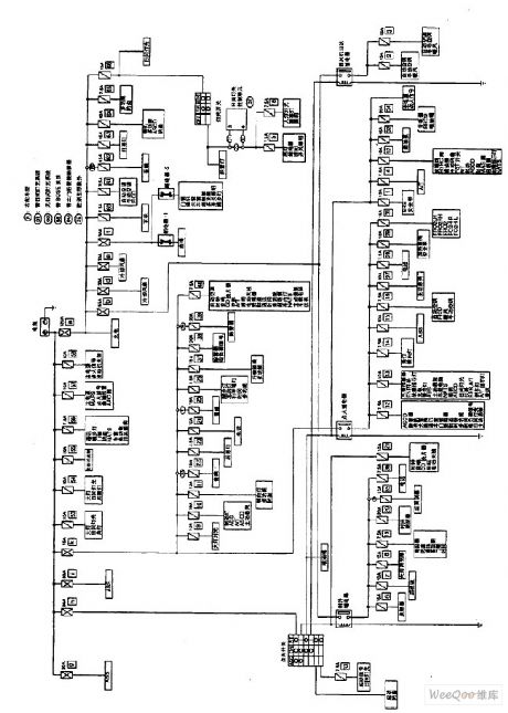
Nissan A32-EL Power Supply Circuit (8)
Published:2011/7/15 5:21:00 Author:Sue | Keyword: Nissan, Power Supply
View full Circuit Diagram | Comments | Reading(773)
Nissan A32-EL Power Supply Circuit (11)
Published:2011/7/15 5:20:00 Author:Sue | Keyword: Nissan, Power Supply
View full Circuit Diagram | Comments | Reading(794)
Nissan A32-EL Rear Foglamp Circuit
Published:2011/7/15 5:25:00 Author:Sue | Keyword: Nissan, Rear Foglamp
View full Circuit Diagram | Comments | Reading(683)
Nissan A32-EL Power Supply Circuit (9)
Published:2011/7/15 5:19:00 Author:Sue | Keyword: Nissan, Power Supply
View full Circuit Diagram | Comments | Reading(785)
Nissan A32-EL Power Supply Circuit (10)
Published:2011/7/15 5:18:00 Author:Sue | Keyword: Nissan, Power Supply
View full Circuit Diagram | Comments | Reading(700)
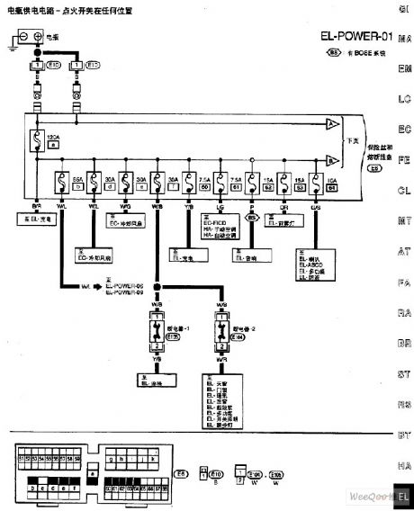
Nissan A32-EL Power Supply Circuit (1)
Published:2011/7/14 7:24:00 Author:Sue | Keyword: Nissan, Power Supply
View full Circuit Diagram | Comments | Reading(744)
Nissan A32-EL Power Supply Circuit (2)
Published:2011/7/14 7:26:00 Author:Sue | Keyword: Nissan, Power Supply
View full Circuit Diagram | Comments | Reading(731)
Nissan A32-EL Power Supply Circuit (3)
Published:2011/7/15 5:37:00 Author:Sue | Keyword: Nissan, Power Supply
View full Circuit Diagram | Comments | Reading(691)
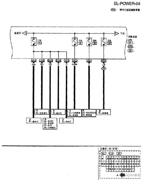
Nissan A32-EL Power Supply Circuit (4)
Published:2011/7/15 5:39:00 Author:Sue | Keyword: Nissan, Power Supply
View full Circuit Diagram | Comments | Reading(703)
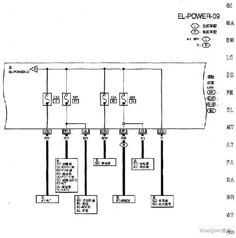
Nissan A32-EL Power Supply Circuit (5)
Published:2011/7/15 5:24:00 Author:Sue | Keyword: Nissan, Power Supply
View full Circuit Diagram | Comments | Reading(663)
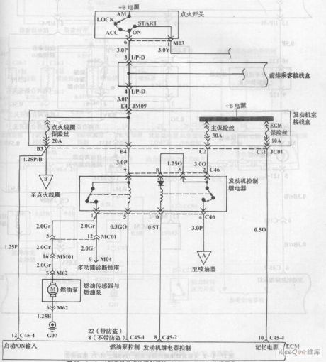
Fuel Injection System(DOHC,M/T) Circuit of Hyundai Sonata 4 Cylinder Engine (1)
Published:2011/7/18 7:54:00 Author:Sue | Keyword: Fuel Injection, System, Hyundai Sonata, 4 Cylinder Engine
View full Circuit Diagram | Comments | Reading(750)
Fuel Injection System(DOHC,M/T) Circuit of Hyundai Sonata 4 Cylinder Engine (2)
Published:2011/7/18 7:55:00 Author:Sue | Keyword: Fuel Injection, System, Hyundai Sonata, 4 Cylinder, Engine
View full Circuit Diagram | Comments | Reading(881)
Fuel Injection System Circuit of Hyundai Sonata with V4 Cylinder Engine (9)
Published:2011/7/18 3:27:00 Author:Sue | Keyword: Fuel Injection, Hyundai Sonata, V4 Cylinder
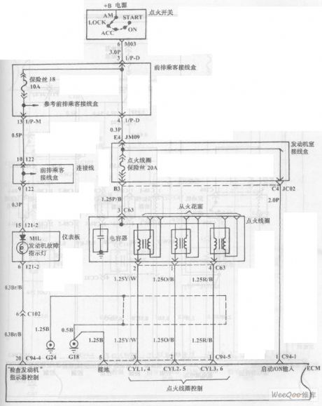
The picture shows the fuel injection system circuit of Hyundai Sonata with V4 cylinder engine. (View)
View full Circuit Diagram | Comments | Reading(787)
Fuel Injection System Circuit of Hyundai Sonata with V4 Cylinder Engine (10)
Published:2011/7/18 3:29:00 Author:Sue | Keyword: Fuel Injection, Hyundai Sonata, V4 Cylinder
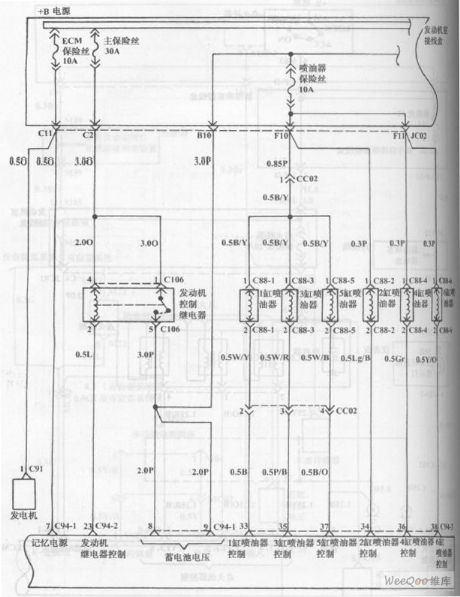
The picture shows the fuel injection system circuit of Hyundai Sonata with V4 cylinder engine. (View)
View full Circuit Diagram | Comments | Reading(743)
The car brake lamp fault monitor (2)
Published:2011/7/23 21:07:00 Author:qqtang | Keyword: brake lamp, fault monitor

The working principle of the circuit (2)The car brake lamp fault monitor consists of resistors R1-R3, diodes VD1 and VD2, NOR gate integrated circuit IC(Dl-D4), LED VL1 and VL2, see as figure 7-54.
S is the car brake lamp switch, HL1 and HL2 are both the car brake lamps.Before the pedal is stepped down, S is in the breakdown state, both VD1 and VD2 are blocked, Nor gates D1 and D3 are both outputting high LEV, both D2 and D4 are outputting low LEV, neither of VL1 and VL2 is glowing. (View)
View full Circuit Diagram | Comments | Reading(1050)
The automobile brake fluid monitor
Published:2011/7/23 4:00:00 Author:qqtang | Keyword: brake fluid monitor
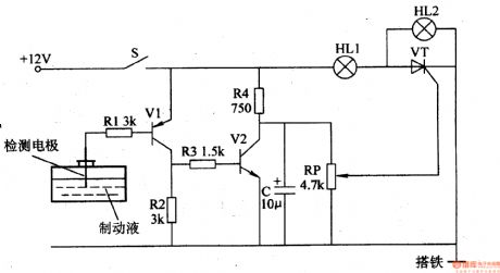
The working principle of the circuit The automobile brake fluid monitor circuit consists of the liquid level detection circuit and storage liquid state indicating circuit, see as figure 7-65.
The liquid level detection circuit consists of the detection polarity, capacitor C, resistors R1-R4, transistors of V1 and V2. The storage fluid state indicating circuit consists of the indicators of HL1 and HL2, potentiometer RP and thyristor VT. When the key S is pressed, the whole machine is getting power and working. (View)
View full Circuit Diagram | Comments | Reading(1911)
The 2.0L(L34) engine, input/output and car speed sensor circuit
Published:2011/7/20 3:35:00 Author:Borg | Keyword: input/output, car speed sensor
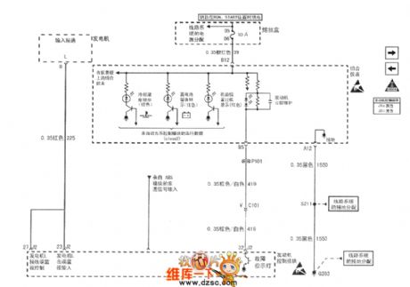
Figure 1. The 2.0L(L34) engine, input/output and car speed sensor circuit of Shanghai GM Buick-Regal
(View)
View full Circuit Diagram | Comments | Reading(1525)
Tiida-BL remote control door system circuit Figure 1
Published:2011/7/14 23:18:00 Author:Fiona | Keyword: remote control, door system
View full Circuit Diagram | Comments | Reading(735)
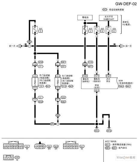
Tiida rear window demister circuit Figure 2
Published:2011/7/14 23:17:00 Author:Fiona | Keyword: rear window demister
View full Circuit Diagram | Comments | Reading(813)
Tiida rear window demister circuit Figure 1
Published:2011/7/14 23:18:00 Author:Fiona | Keyword: rear window demister
View full Circuit Diagram | Comments | Reading(1167)
| Pages:15/47 1234567891011121314151617181920Under 20 |
Circuit Categories
power supply circuit
Amplifier Circuit
Basic Circuit
LED and Light Circuit
Sensor Circuit
Signal Processing
Electrical Equipment Circuit
Control Circuit
Remote Control Circuit
A/D-D/A Converter Circuit
Audio Circuit
Measuring and Test Circuit
Communication Circuit
Computer-Related Circuit
555 Circuit
Automotive Circuit
Repairing Circuit


