
555 Circuit
Index 4
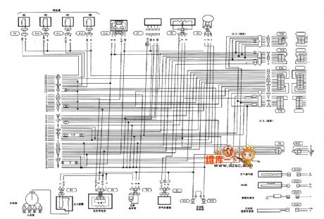
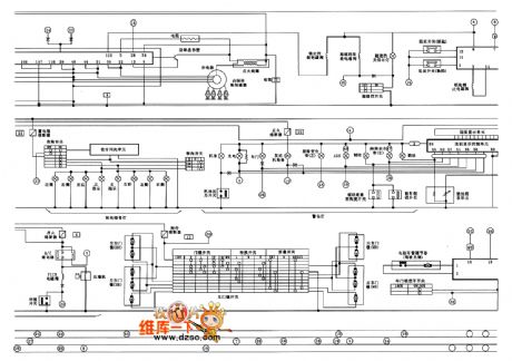
Beijing Hyundai Sang Nata MFI Control System (DOHC, M / T) Schematic
Published:2013/12/25 20:12:00 Author:lynne | Keyword: Beijing Hyundai Sang Nata MFI Control System (DOHC, M / T) Schematic,
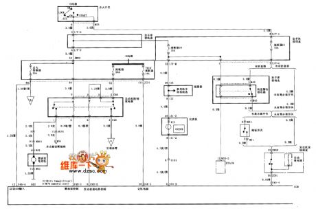
Beijing Hyundai Sang Nata MFI Control System (DOHC, M / T) Schematic as follows:
(View)
View full Circuit Diagram | Comments | Reading(1030)
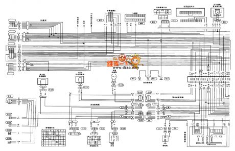
Beijing Hyundai Sang Nata MFI Control System (DOHC, M / T) Schematic (one)
Published:2013/12/25 20:10:00 Author:lynne | Keyword: Beijing Hyundai Sang Nata MFI Control System (DOHC, M / T) Schematic (one),
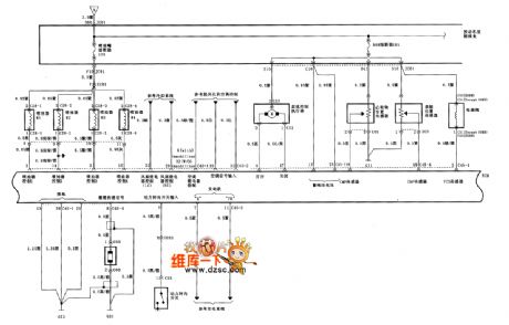
Beijing Hyundai Sang Nata MFI Control System (DOHC, M / T) Schematic (one) as follows:
(View)
View full Circuit Diagram | Comments | Reading(735)
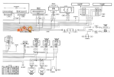
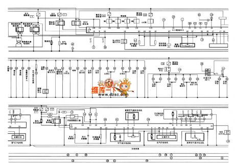
Beijing Hyundai Sang Nata MFI Control System (DOHC, M / T) Schematic (two)|
Published:2013/12/25 20:08:00 Author:lynne | Keyword: Beijing Hyundai Sang Nata MFI Control System (DOHC, M / T) Schematic (two),
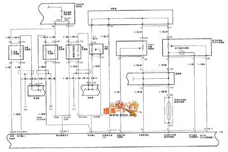
Beijing Hyundai Sang Nata MFI Control System (DOHC, M / T) Schematic (two) as follows:
(View)
View full Circuit Diagram | Comments | Reading(646)
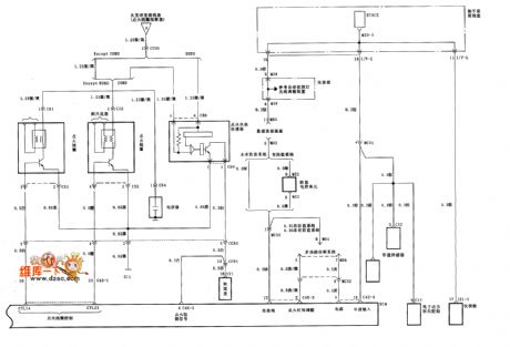
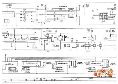
Beijing Hyundai Sang Nata MFI Control System (DOHC, M / T) Schematic (three)
Published:2013/12/25 20:03:00 Author:lynne | Keyword: Beijing Hyundai Sang Nata MFI Control System (DOHC, M / T) Schematic (three),

Beijing Hyundai Sang Nata MFI Control System (DOHC, M / T) Schematic (three) as follows:
(View)
View full Circuit Diagram | Comments | Reading(693)
Beijing Hyundai Sang Nata MFI Control System (DOHC, M / T) Schematic (four)
Published:2013/12/25 20:04:00 Author:lynne | Keyword: Beijing Hyundai Sang Nata MFI Control System (DOHC, M / T) Schematic (four),
Beijing Hyundai Sang Nata MFI Control System (DOHC, M / T) Schematic (four) as follows:
(View)
View full Circuit Diagram | Comments | Reading(973)
Fengshen Bluebird EQ7200-Ⅱ car circuit diagram
Published:2013/12/11 20:26:00 Author:lynne | Keyword: Fengshen Bluebird EQ7200-Ⅱ car circuit diagram
Fengshen Bluebird EQ7200-Ⅱ car circuit diagram is shown below:
(View)
View full Circuit Diagram | Comments | Reading(874)
Fengshen Bluebird EQ7200-Ⅱ car circuit diagram (one)
Published:2013/12/11 20:25:00 Author:lynne | Keyword: Fengshen Bluebird EQ7200-Ⅱ car circuit diagram (one) ,

Fengshen Bluebird EQ7200-Ⅱ car circuit diagram (one) as follows:
(View)
View full Circuit Diagram | Comments | Reading(782)
Fengshen Bluebird EQ7200-Ⅱ car circuit diagram (two)
Published:2013/12/11 20:28:00 Author:lynne | Keyword: Fengshen Bluebird EQ7200-Ⅱ car circuit diagram (two)

Fengshen Bluebird EQ7200-Ⅱ car circuit diagram (two) as follows:
(View)
View full Circuit Diagram | Comments | Reading(662)
Fengshen Bluebird EQ7200-Ⅱ car circuit diagram (three)
Published:2013/12/11 19:43:00 Author:lynne | Keyword: Fengshen Bluebird EQ7200-Ⅱ car circuit diagram (three),
Fengshen Bluebird EQ7200-Ⅱ car circuit diagram (three) as follows:
(View)
View full Circuit Diagram | Comments | Reading(744)
Fengshen Bluebird EQ7200-Ⅱ ECCS car circuit diagram
Published:2013/12/11 19:41:00 Author:lynne | Keyword: Fengshen Bluebird EQ7200-Ⅱ ECCS car circuit diagram,

Fengshen Bluebird EQ7200-Ⅱ ECCS car circuit diagram is shown below:
(View)
View full Circuit Diagram | Comments | Reading(793)
Fengshen Bluebird EQ7200-Ⅱ sedan ECCS Diagram (three)
Published:2013/12/10 20:47:00 Author:lynne | Keyword: Fengshen Bluebird EQ7200-Ⅱ sedan ECCS Diagram (three),
Fengshen Bluebird EQ7200-Ⅱ sedan ECCS Diagram (three) as follows:
(View)
View full Circuit Diagram | Comments | Reading(613)
Fengshen Bluebird EQ7200-Ⅱ sedan ECCS circuit diagram (two)
Published:2013/12/10 20:48:00 Author:lynne | Keyword: Fengshen Bluebird EQ7200-Ⅱ sedan ECCS circuit diagram (two),
Fengshen Bluebird EQ7200-Ⅱ sedan ECCS circuit diagram (two) as follows:
(View)
View full Circuit Diagram | Comments | Reading(746)
Fengshen Bluebird EQ7200-Ⅱ sedan ECCS Diagram (one)
Published:2013/12/10 20:49:00 Author:lynne | Keyword: Fengshen Bluebird EQ7200-Ⅱ sedan ECCS Diagram (one),
Fengshen Bluebird EQ7200-Ⅱ sedan ECCS Diagram (one) as follows:
(View)
View full Circuit Diagram | Comments | Reading(722)
Fengshen Bluebird EQ7200-Ⅱ sedan ECCS Diagram (five)
Published:2013/12/10 20:45:00 Author:lynne | Keyword: Fengshen Bluebird EQ7200-Ⅱ sedan ECCS Diagram (five),

Fengshen Bluebird EQ7200-Ⅱ sedan ECCS Diagram (five) as follows:
(View)
View full Circuit Diagram | Comments | Reading(612)
Fengshen Bluebird EQ7200-Ⅱ sedan ECCS circuit (four)
Published:2013/12/10 20:46:00 Author:lynne | Keyword: Fengshen Bluebird EQ7200-Ⅱ sedan ECCS circuit (four),


Fengshen Bluebird EQ7200-Ⅱ sedan ECCS circuit (four) as follows:
(View)
View full Circuit Diagram | Comments | Reading(642)
555 Low Voltage Operation
Published:2013/11/4 20:17:00 Author:lynne | Keyword: 555 Low Voltage Operation
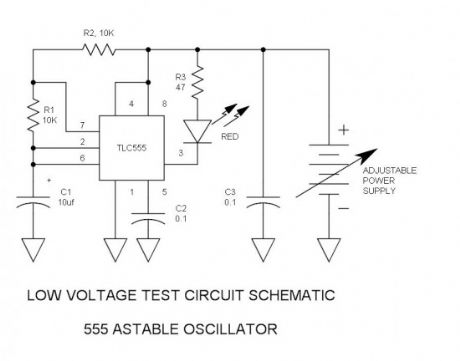
I had heard some stories in the past concerning how poorly the 555 ran below Vcc = 5V, so I embarked on an endeavor to see if I could improve operation. The spec sheet specifies minimum Vcc at 4.5V and I tended to believe it. I set up a simple test circuit and ran each of 5 different bipolar 555 devices while varying Vcc. What I learned surprised me. Not only did it run substantially below 5V, but it ran well. Then I tried a CMOS 555 and that worked below 1V.
555 Test Circuit Schematic
(View)
View full Circuit Diagram | Comments | Reading(952)
555 Duty Cycle Control
Published:2013/10/31 22:07:00 Author:lynne | Keyword: 555 Duty Cycle Control

Here is a simple oscillator circuit that varies the duty cycle over a wide range without affecting the frequency. It is a variation of the simple 555 astable oscillator. Initially, I told a reader that there was no standard 555 circuit that could do this, but then the grey matter started working. The use of an air-variable capacitor for frequency control is a mind-blower—nothing short of a time warp!
555 Duty Cycle Control Schematic
Overview
When potentiometer R1 is centered, operation is obvious and the duty cycle is 50%. However, as R1 is rotated in either direction the charge time and discharge times vary accordingly. The two sides of R1 have independent steering diodes (D1 & D2). C1 & C2 make up the timing capacitor. Pins 2 & 6 of the 555 are the upper and lower thresholds of the input comparators. The charge /discharge voltage is taken from pin 3 because it has rail-to-rail voltage swing, and the open collector output (pin 7) cannot do this. The rectangular waveform output is taken from pin 7 instead. R3 is the pull-up resistor.
If constant frequency is desired, C1 could be padded for the correct frequency. However, most experimenters also want variable frequency. Since R1 cannot be varied in total resistance, it cannot vary the frequency. R2 could vary the frequency, but would also affect the duty cycle ratio limits as well. The only practical means of obtaining variable frequency is to vary C1.
Mathematical proof
Q = I * T – where Q is the charge, I is charge current and T is charge time
Q = C * V – where Q is charge, C is capacitance, and V is voltage across the capacitor
∴ I * T = C * V
E = I * R – where E is voltage I is current and R is resistance
∴ I * T = C * I * R – because E is simply another expression for V
T = C * R – dividing by I—we have now proved that charge time is directly proportional to R
So we have a charge resistance and a discharge resistance, the sum of which is constant and equal to the R1 potentiometer total resistance (1 to 3). Therefore, the sum of the charge and discharge times is also constant. Since F = 1/T, the frequency is also be constant.
In other words, the two resistances are complementary and the two time periods are likewise complementary.
The Air Variable Capacitor
The old-fashioned air variable capacitor is old and klunky. While DigiKey offers no such product, these devices remain available on eBay as used or old stock. Every serious experimenter should have one of these. The one I would buy is a 3-gang 440pf. Wired in parallel the total capacitance is 1320pf. Physical size limitations prevent higher capacitances.
Actually, it is fun to play with air variable capacitors.
High impedances
To obtain a reasonably low frequency, R1 had to be selected to have as high a resistance as possible. 2M is the highest value pot I had on hand. A 5M would also be a good selection. To function under such high impedance conditions, I selected the TLC555 CMOS 555. A further advantage of this device is that it has rail-to-rail output voltage—something that the bipolar 555 cannot do.
Limits of accuracy
The accuracy tends to degrade when the slew rate at C1 exceeds about 0.25V/uS. When this happens, the propagation delay of the comparators becomes significant and the frequency drops somewhat. This causes the peaks of the saw-tooth waveform to “skid” past the thresholds before the output switches polarity. This forces the maximum frequency to be lower than about 50kHZ for 50% duty cycle, or lower than 2kHZ with 98% duty cycle. To maintain 1 or 2% frequency accuracy the duty cycle range must drop as frequency increases.
(View)
View full Circuit Diagram | Comments | Reading(1295)
Quirky 555 Timer Reset Function
Published:2013/10/13 20:39:00 Author:lynne | Keyword: Quirky 555 Timer Reset Function

How many have had legitimate problems with the 555 timer? Let me guess…it involved the reset line, did it not? We all know that pin 4 must be set high before oscillation begins, but what is its threshold? input current? and what happens when it is operated slightly out of spec? This may be the very first attempt in documentation of this obscure phenomenon.
555 pin 4 reset behavior schematic
Method
To determine reset threshold, a transistor integrator generates a low impedance, negative-going ramp voltage signal that integrates from +5V to –0.65V. To obtain the negative voltage, the power supply is split to provide –0.7V. While it is slowly changing at the rate of -1V /S (trace 1), pins 2 & 6 are monitored for oscillation (trace 2). A 3rd trace monitors the output (pin 3). All data is logged on the spreadsheet.
A total of (8) devices were tested, including (2) CMOS TLC555N devices.When running, the 555 oscillates at approx. 100hZ. Vcc = 5V. (View)
View full Circuit Diagram | Comments | Reading(1088)
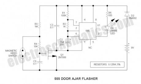
555 Door Ajar Flasher
Published:2013/10/11 20:52:00 Author:lynne | Keyword: 555 Door Ajar Flasher
How it works
The flasher is the standard 555 oscillator circuit that drives an ultrabright white LED for daylight visibility. Repetition rate is about 2hZ and the duty cycle is about 10%. Peak LED current is 60mA, but average is 6mA.
Since the door is supposed to remain closed most of the time, the circuit power is controlled by a 2N7000 N Channel MOSFET. When the reed switch is closed (sensing the magnet), it shorts out the gate drive signal to the transistor and turns off the oscillator. At this time the battery drain is only 9uA.
Note that there seems to be no convenient way to turn off the 555 in such a way that it does not draw much current. Grounding pin 4 stops oscillation, but turns on the LED continuously.
C2 provides voltage transient protection for the MOSFET gate.
LED brightness is controlled by R5—YIKES! do not look into the LED like I did…
The reed switch
This circuit uses the commonly available NC (normally closed) reed switch. A NO variety would be easier to use, but such is rare and expensive. If the circuit is packaged inside a small plastic enclosure, the reed switch could be cemented into one edge of the box thus protecting the glass tube from damage. The reed switch I used for the test is packaged in a plastic tube. It is quite sensitive — can sense the magnet at 2 to 3cm. (View)
View full Circuit Diagram | Comments | Reading(954)
555 Christmas Lights
Published:2013/10/11 20:50:00 Author:lynne | Keyword: 555 Christmas Lights

Though a Christian by personal faith in Jesus Christ, I am not big on Christmas decorations except for the traditional Christmas tree. However, this 555 flasher project is an exception. This is a take-off on the previous Firefly Lights Circuit posting. I had a strip of four tiny PCB’s remaining, so I built them up before separating them — and never did separate after observing operation. The result is nothing short of amazing. Instead of boring repetitive (predictable) flashing, they are in no way synchronous. This makes for a captivating watch — something like watching a fire… Hang this on your Christmas tree as an ornament. (View)
View full Circuit Diagram | Comments | Reading(1197)
| Pages:4/47 1234567891011121314151617181920Under 20 |
Circuit Categories
power supply circuit
Amplifier Circuit
Basic Circuit
LED and Light Circuit
Sensor Circuit
Signal Processing
Electrical Equipment Circuit
Control Circuit
Remote Control Circuit
A/D-D/A Converter Circuit
Audio Circuit
Measuring and Test Circuit
Communication Circuit
Computer-Related Circuit
555 Circuit
Automotive Circuit
Repairing Circuit