TXS0101DRLR, TXS0101YZPR, TXS0102DCTR Selling Leads, Datasheet
MFG:Texas Instruments (VA) Category:Integrated Circuits (ICs) D/C:2009+

TXS0101DRLR, TXS0101YZPR, TXS0102DCTR Datasheet download

Part Number: TXS0101DRLR
Category: Integrated Circuits (ICs)
MFG: Texas Instruments (VA)
Package Cooled:
D/C: 2009+
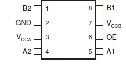
Description: IC VOLT-LVL TRANSL 2BIT BI SM8
Price Break
1
25
100
250
500
1000
Unit Price
.80000
.60000
.45000
.33200
.28000
.26600
Extended Price
0.80
15.00
45.00
83.00
140.00
266.00
(All prices are in USD) Prices for reference only