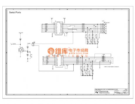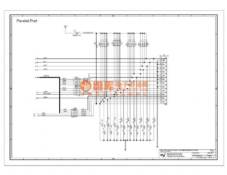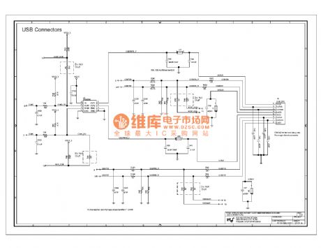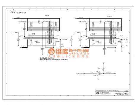
Circuit Diagram
Index 446
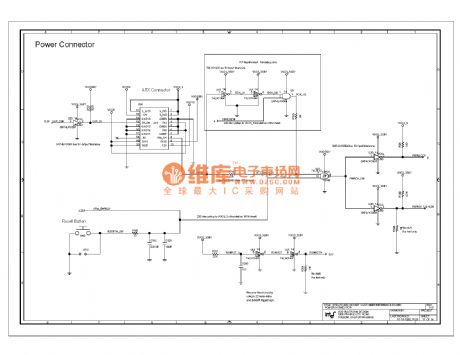
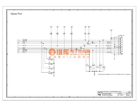
820e computer motherboard circuit diagram 32
Published:2011/10/24 20:25:00 Author:Ecco | Keyword: computer motherboard
View full Circuit Diagram | Comments | Reading(889)
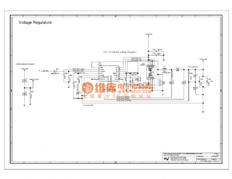
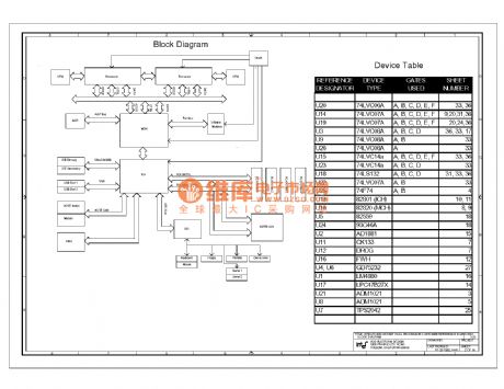
820e computer motherboard circuit diagram 26
Published:2011/10/24 20:36:00 Author:Ecco | Keyword: computer motherboard
View full Circuit Diagram | Comments | Reading(742)
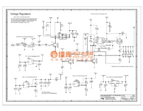
820e computer motherboard circuit diagram 25
Published:2011/10/24 20:36:00 Author:Ecco | Keyword: computer motherboard
View full Circuit Diagram | Comments | Reading(998)
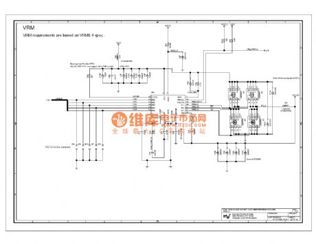
820e computer motherboard circuit diagram 24
Published:2011/10/24 20:35:00 Author:Ecco | Keyword: computer motherboard
View full Circuit Diagram | Comments | Reading(688)
820e computer motherboard circuit diagram 23
Published:2011/10/24 20:34:00 Author:Ecco | Keyword: computer motherboard
View full Circuit Diagram | Comments | Reading(723)
820e computer motherboard circuit diagram 22
Published:2011/10/24 20:34:00 Author:Ecco | Keyword: computer motherboard
View full Circuit Diagram | Comments | Reading(720)
820e computer motherboard circuit diagram 31
Published:2011/10/24 20:24:00 Author:Ecco | Keyword: computer motherboard
View full Circuit Diagram | Comments | Reading(689)
820e computer motherboard circuit diagram 30
Published:2011/10/24 20:38:00 Author:Ecco | Keyword: computer motherboard
View full Circuit Diagram | Comments | Reading(699)
820e computer motherboard circuit diagram 29
Published:2011/10/24 20:38:00 Author:Ecco | Keyword: computer motherboard
View full Circuit Diagram | Comments | Reading(876)
820e computer motherboard circuit diagram 28
Published:2011/10/24 20:37:00 Author:Ecco | Keyword: computer motherboard
View full Circuit Diagram | Comments | Reading(713)
820e computer motherboard circuit diagram 27
Published:2011/10/24 20:37:00 Author:Ecco | Keyword: computer motherboard
View full Circuit Diagram | Comments | Reading(664)
820e computer motherboard circuit diagram 41
Published:2011/10/24 20:30:00 Author:Ecco | Keyword: computer motherboard
View full Circuit Diagram | Comments | Reading(744)
820e computer motherboard circuit diagram 42
Published:2011/10/24 20:30:00 Author:Ecco | Keyword: computer motherboard
View full Circuit Diagram | Comments | Reading(858)
820e computer motherboard circuit diagram 43
Published:2011/10/24 20:31:00 Author:Ecco | Keyword: computer motherboard
View full Circuit Diagram | Comments | Reading(731)
Fowl hatching electron constant temperature control circuit using TC621 temperature sensor
Published:2011/10/20 2:19:00 Author:Rebekka | Keyword: Fowl hatching , electron constant temperature , temperature sensor

Chicken egg incubation temperature requires 36 ~ 39oC temperature range. Temperature sensing integrated circuits uses TC621 temperature control circuit with fewer external components. The features are: Low cost, high reliability etc. You can set upper and lower temperature, and it is convenient to adjust. The circuit is shown as above. It consists of temperature sensor TC621, upper and lower limit , temperature indicator, relay controlling heatingcircuit,analog hen cackling sound circuit, audio amplifier circuit and the AC step-down rectifier circuit.
(View)
View full Circuit Diagram | Comments | Reading(1429)
Beijing grand cherokee car charging system circuit diagram
Published:2011/10/20 2:12:00 Author:Rebekka | Keyword: Beijing grand cherokee, car charging system
View full Circuit Diagram | Comments | Reading(857)
Electrical apparatus start-stop circulatory timer circuit diagram
Published:2011/10/20 21:40:00 Author:Rebekka | Keyword: Electrical apparatus , start-stop circulatory timer

LM555 integrated circuit forms the basic duty cycle adjustable multivibrator. Discharge and charge circuit of C3 are connected to KH1, W1, KH2, W2 respectively in series for coarse tuning, fine-tuning the stop time. When the circuit starts to work, the power supply passes R3, HK1 series resistor and W1, V2 to C3, thenIC's pin 3 outputs high level. LED emitslight and the relay pulls in. Its contacts areconnected to the load. When the voltage on C3 rises to 2 / 3 supply voltage, IC flips, relay releases. Meanwhile, C3 passes V3, R4, HK2 and IC's 7 feet discharges power to the ground. When the voltage C3 drops to 1 / 3 supply voltage, IC flips and relay pulls in. So the cycle starts to work. Each block of HK1 and HK2 increase or decrease for 4.5 minutes. The adjustment range of W1, W2 is about 0 to 5 minutes. (View)
View full Circuit Diagram | Comments | Reading(2303)
Rolling radio control circuit(TH150/TH150A/B)
Published:2011/10/19 22:32:00 Author:Rebekka | Keyword: Rolling radio control

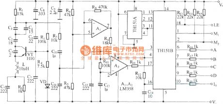
The internal structure of rolling code encoder circuit is complex. Its encoded mode is special. But its usage is the same with digital coding circuit and even more simple. The radio control circuit is composed of rolling code decoding circuits TH150/TH151A. The circui is shown as above.
Super-regenerative wireless remote control receiver circuit(rolling decoding circuit TH151A / B ). (View)
View full Circuit Diagram | Comments | Reading(1928)
Valuables pilfering tracker circuit diagram 1 (KD400/JD400)
Published:2011/10/19 22:28:00 Author:Rebekka | Keyword: valuables pilfering tracker
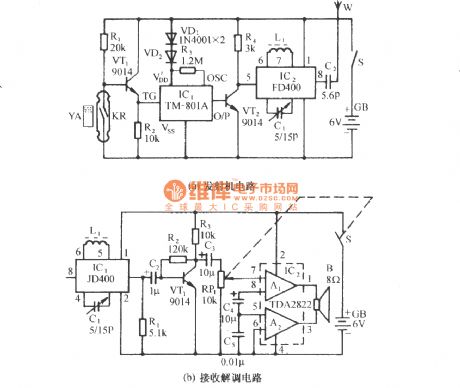
The circuit is shown as figure. It contains wireless Voice FM transmitter and wireless receiver, decoder.The transmitter is placed in the shellof precious appliances. It will automatically launch whistle sound frequency modulation (FM) radio signals. when the appliance is moved, the owner will get the signal by receiver. It will follow the stolen things untill the theft is caught. When someone is moving the valuables, KR and YA will be departed. The touch spot of reed switch will be cut. The TV1 gets bias current and be turned on. Pulse high jump is added to trigger control terminal TG of IC1to trigger itand make a sound. Figure B is receiver demodulation circuit. (View)
View full Circuit Diagram | Comments | Reading(3888)
Simple and practical mouse remote control circuit diagram
Published:2011/10/19 22:21:00 Author:Rebekka | Keyword: Simple and practical mouse remote
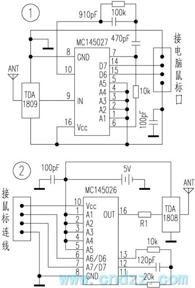
Generally, there are 4 circuit connection lines in the mouse and computer(the circuit device can accept up to four input data lines, and readers can select their own actual situation). They are the positive power supply, the data line 1, the data line 2. We will cut off the mouse connection to find out the four lines respectively. And we use the receiving end D6 and D7 of MC145026 encoded data transmission circuit data lines to receive the data sent by mouse lines 1 and 2. It will send the conversion data in the output of the chips D6 and D7, andyou do not need to change the mouse and computer of the circuit. And you don't need to install additional mouse drive software. All the features of the original mouse can also be used normally. (View)
View full Circuit Diagram | Comments | Reading(2544)
| Pages:446/2234 At 20441442443444445446447448449450451452453454455456457458459460Under 20 |
Circuit Categories
power supply circuit
Amplifier Circuit
Basic Circuit
LED and Light Circuit
Sensor Circuit
Signal Processing
Electrical Equipment Circuit
Control Circuit
Remote Control Circuit
A/D-D/A Converter Circuit
Audio Circuit
Measuring and Test Circuit
Communication Circuit
Computer-Related Circuit
555 Circuit
Automotive Circuit
Repairing Circuit


