Time Control
Electrical apparatus start-stop circulatory timer circuit diagram
Published:2011/10/20 21:40:00 Author:Rebekka | Keyword: Electrical apparatus , start-stop circulatory timer | From:SeekIC
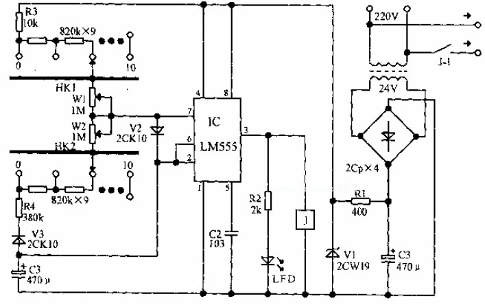
LM555 integrated circuit forms the basic duty cycle adjustable multivibrator. Discharge and charge circuit of C3 are connected to KH1, W1, KH2, W2 respectively in series for coarse tuning, fine-tuning the stop time. When the circuit starts to work, the power supply passes R3, HK1 series resistor and W1, V2 to C3, thenIC's pin 3 outputs high level. LED emitslight and the relay pulls in. Its contacts areconnected to the load. When the voltage on C3 rises to 2 / 3 supply voltage, IC flips, relay releases. Meanwhile, C3 passes V3, R4, HK2 and IC's 7 feet discharges power to the ground. When the voltage C3 drops to 1 / 3 supply voltage, IC flips and relay pulls in. So the cycle starts to work. Each block of HK1 and HK2 increase or decrease for 4.5 minutes. The adjustment range of W1, W2 is about 0 to 5 minutes.
Reprinted Url Of This Article:
http://www.seekic.com/circuit_diagram/Control_Circuit/Time_Control/Electrical_apparatus_start_stop_circulatory_timer_circuit_diagram.html
Print this Page | Comments | Reading(3)

Article Categories
power supply circuit
Amplifier Circuit
Basic Circuit
LED and Light Circuit
Sensor Circuit
Signal Processing
Electrical Equipment Circuit
Control Circuit
Remote Control Circuit
A/D-D/A Converter Circuit
Audio Circuit
Measuring and Test Circuit
Communication Circuit
Computer-Related Circuit
555 Circuit
Automotive Circuit
Repairing Circuit
Code: