
Circuit Diagram
Index 455
Sub-ultrasonic remote control switch circuit 1
Published:2011/9/26 1:55:00 Author:Rebekka | Keyword: Sub-ultrasonic remote control switch

This example describes the sub-ultrasonic remote control switch. It uses pressurized gas-type sub-ultrasonic flute (It is made of rubber with olive and flat round) control. Pinch the ultrasonic whistle and the switch will be closed. The sub-ultrasonic remote control switches can be used to control lighting, exhaust fan and some minor electrical equipment. The ultrasonic remote control switch circuit is composed of the sub-circuit, the power supply, sub-ultrasonic control circuit, bistable trigger and control implementation circuit. Here is the circuit.
Components selection R1 uses 1/2W metal film resistors; R2 ~ R11 use 1/4W carbon film resistors use or metal film resistors. C1 uses 400Vpolyester capacitor or CBB capacitor; C2, C4, C5, C7 and C8 use aluminium electrolytic capacitors with thevoltage in 16V; C3 and C6 use monolithic capacitors. VD1 and VD2 use 1N4007 silicon rectifier diodes; VD3 ~ VD5 uses 1N4148 silicon switching diode. VS uses 1W, 9V voltage silicon diode. VL uses φ3mm green light-emitting diodes. (View)
View full Circuit Diagram | Comments | Reading(1344)
Multi-control switch circuit diagram 2
Published:2011/9/26 1:56:00 Author:Rebekka | Keyword: Multi-control switch circuit

This example describes the multi-control switch. It uses multi-way switch to control one rout light(which may be more bulbs in parallel). It applies to hotels, rooms, corridors and the corridor and other places. The multi-control switch circuit is composed of the control switch S1 ~ S6 EL composition and lighting. The circuit is shown as above.
S1 uses single-pole switch or bipolar switches with contact current capacity in1OA. S2 and S6 usedouble-pole (SPDT) switch. S3 ~ S5 use optional double-pole (DPDT) switch.
(View)
View full Circuit Diagram | Comments | Reading(801)
Multi-control switch circuit diagram 3
Published:2011/9/26 1:59:00 Author:Rebekka | Keyword: Multi-control switch

This example describes a multi-place control switch with time delay function,which usesmulti-buttons to control one rout light. Pressing any button can lit the light, the lights will be automatically turn off hin about 3mins. The switch circuit is compose of S1 ~ S5, power circuit and timing control circuit. The circuit is shown as the chart.
Somponent selection.R1 and R2 use 1/4W or 1/8W carbon film resistors. C1 and C2 select aluminum electrolytic capacitors with voltage in 25V. VD uses 1N4001 or 1N4007 type silicon rectifier diodes. IC uses NE555 type time-base integrated circuit.
(View)
View full Circuit Diagram | Comments | Reading(731)
Multi-control switch circuit diagram 4
Published:2011/9/26 2:02:00 Author:Rebekka | Keyword: Multi-control switch circuit

This example describes the multi-place control switch, you can turn on or off any partial load(electrical equipment) of the working power source. The switch can be used for corridor, public areas lighting control. It can also be used for industrial production (more than one place on the factory floor control of a set of production equipment). The multi-place control switch circuit consists of intermediate relays KA1 ~ KA3 and S1 ~ Sn. It is shown as picture.
If you need to control the power of a larger load, you can use AC contactor to replace KA1. Components selection: S1~Sn selects moving together (normally open) buttons. KA1 ~ KA3 select 220V AC relays.
(View)
View full Circuit Diagram | Comments | Reading(760)
Multi-control switch circuit diagram 5
Published:2011/9/16 0:57:00 Author:Rebekka | Keyword: multi-control switch

Multi-control switch circuit diagram.
This example describes the multi-control switch whichcan be used to control lights or low-power single-phase AC motor. The control switch circuit of the step-down circuit and control circuit, and it isshown in Figure 34.
Components selection. R1, R3 and R4 select 1/4W metal film resistors; R2 uses 1/2W metal film resistors. C1 selects monolithic capacitors; C2 uses electrolytic capacitor with thevoltage in 16V. IC uses 7-bit binary counter CD4024 IC. If the controlled lightisbelow 100W, the UR and VT can choose 1A, 400V reactor and thyristor rectifier bridge; If the single-phase AC motors is controlled under 1kW, the UR and the current capacity of VT should be 6 ~ 10A.
(View)
View full Circuit Diagram | Comments | Reading(1451)
Multi-control switch circuit diagram 1
Published:2011/9/26 2:08:00 Author:Rebekka | Keyword: Multi-control switch circuit

This example describes the multi-place control switch, you can use multi-button switch control one route electrical appliances (eg lights). It applies to hotels, hospitals, corridors, staircases and other more than 3-way switch controlling situation. The circuitis composed ofthe power supply circuit, monostable, bistable trigger, and buttons S1 ~ Sn, thyristor VT etc.Components select.R1 selects 1/2W carbon film resistors or metal film resistors; R2 ~ R4 select 1/4W carbon film resistors. C1 selects polyester capacitor or CBB capacitor with withstand voltage being greater than 400V; C2 uses 25V electrolytic capacitor; C3 uses monolithic capacitors or polyester capacitors. VD selects 1N4007 silicon rectifier diode. VS selects 1/2W, 9V voltage silicon diode. VT selects 3A, 600V bi-directional thyristor. IC selects CD4013 or C043 dual D flip-flop integrated circuits. S1 ~ Sn select normally open buttons.
(View)
View full Circuit Diagram | Comments | Reading(1118)
The electronic filter circuit diagram for microphone power supply
Published:2011/8/24 2:27:00 Author:Jessie | Keyword: Microphone power supply, electronic filter
View full Circuit Diagram | Comments | Reading(745)
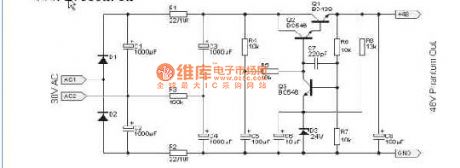
Hi fi audio power amplifier circuit
Published:2011/8/24 2:26:00 Author:Jessie | Keyword: Hi fi audio power amplifier

Hi fi audio power amplifier circuit: if you want to get high quality recording, you should have a good phone,but you must use high quality amplifier. This amplifier uses the tiny distortion ne5534, and itis listening to be soft and delicate. (View)
View full Circuit Diagram | Comments | Reading(995)
INA163 Microphone amplifier circuit diagram
Published:2011/8/24 2:24:00 Author:Jessie | Keyword: Microphone amplifier

View full Circuit Diagram | Comments | Reading(1576)
Cadillac electronic suspension circuit diagram( road-sensing suspension)
Published:2011/8/24 2:23:00 Author:Jessie | Keyword: Cadillac electronic suspension, road-sensing suspension

View full Circuit Diagram | Comments | Reading(737)
Buick engine performance circuit diagram(3.8l,vink)
Published:2011/8/19 1:10:00 Author:Jessie | Keyword: Buick , engine performance, 3.8l,vink

View full Circuit Diagram | Comments | Reading(790)
Buick engine performance circuit diagram(3.8l,vin1)
Published:2011/8/19 1:07:00 Author:Jessie | Keyword: Buick , engine performance , 3.8l,vin1

View full Circuit Diagram | Comments | Reading(549)
Double op-amp realization circuit diagram 3
Published:2011/8/19 1:05:00 Author:Jessie | Keyword: Double op-amp realization

View full Circuit Diagram | Comments | Reading(665)
Double op-amp realization circuit diagram 2
Published:2011/8/19 1:05:00 Author:Jessie | Keyword: Double op-amp realization

View full Circuit Diagram | Comments | Reading(609)
Double op-amp realization circuit diagram 1
Published:2011/8/19 1:04:00 Author:Jessie | Keyword: Double op-amp realization

View full Circuit Diagram | Comments | Reading(747)
Single op-amp realization circuit diagram
Published:2011/8/19 2:04:00 Author:Jessie | Keyword: Single op-amp realization

If it uses the band-pass filter composed of the components with parameters being very closed, it is prone to oscillation. The resistor connected to should be selected in E-96 1% series, or you will destroy the oscillation conditions. (View)
View full Circuit Diagram | Comments | Reading(663)
Cadillac wiper washer circuit diagram( with rain sensor)
Published:2011/8/19 2:09:00 Author:Jessie | Keyword: Cadillac , wiper washer, rain sensor

View full Circuit Diagram | Comments | Reading(1158)
Sallen - Key specific filter circuit diagram
Published:2011/8/19 2:08:00 Author:Jessie | Keyword: Sallen - Key, specific filter
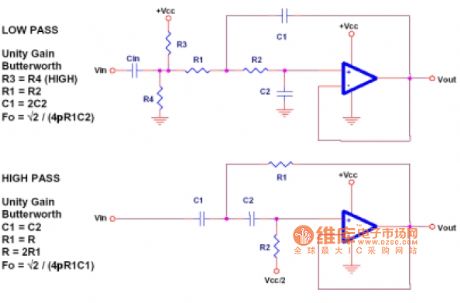
This circuit is an unity-gain circuit, which canchange gain of the filter Sallen - Keyand theamplitude-frequency characteristics and types of filter. In fact, Sallen - Key specific filter isa butterworth filterwith thegain in 1. (View)
View full Circuit Diagram | Comments | Reading(1190)
Panasonic NV-450 VCR system modification circuit diagram
Published:2011/8/22 3:26:00 Author:Jessie | Keyword: Panasonic , VCR system , modification circuit
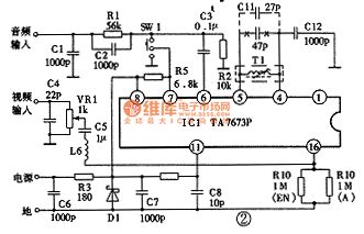
Panasonic NV-450 VCR system modification circuit diagram is shown as the chart. TA7673P is a special radio frequency modulation integrated circuit, and its sound carrier frequency is 5.5 MHz. T1 and Cllare connected tothe pin 4andpin5 of rf modulation integrated circuits, which can determine the oscillation frequencyof voices. Therefore, the method ofchanging sound carrier frequency from 5.5 MHz to 6.5 MHz is: change C11 of LC resonant circuit from 47p to 27p, then connect VCR with television, let video replay a box of good video, then watch videos as side trimming the magnetic cores of Tl to make the sound best. (View)
View full Circuit Diagram | Comments | Reading(2262)
Cadillac power circuit
Published:2011/8/22 3:28:00 Author:Jessie | Keyword: Cadillac power

View full Circuit Diagram | Comments | Reading(496)
| Pages:455/2234 At 20441442443444445446447448449450451452453454455456457458459460Under 20 |
Circuit Categories
power supply circuit
Amplifier Circuit
Basic Circuit
LED and Light Circuit
Sensor Circuit
Signal Processing
Electrical Equipment Circuit
Control Circuit
Remote Control Circuit
A/D-D/A Converter Circuit
Audio Circuit
Measuring and Test Circuit
Communication Circuit
Computer-Related Circuit
555 Circuit
Automotive Circuit
Repairing Circuit