Basic Circuit
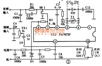
Panasonic NV-450 VCR system modification circuit diagram
Published:2011/8/22 3:26:00 Author:Jessie | Keyword: Panasonic , VCR system , modification circuit | From:SeekIC

Panasonic NV-450 VCR system modification circuit diagram is shown as the chart. TA7673P is a special radio frequency modulation integrated circuit, and its sound carrier frequency is 5.5 MHz. T1 and Cllare connected tothe pin 4andpin5 of rf modulation integrated circuits, which can determine the oscillation frequencyof voices. Therefore, the method ofchanging sound carrier frequency from 5.5 MHz to 6.5 MHz is: change C11 of LC resonant circuit from 47p to 27p, then connect VCR with television, let video replay a box of good video, then watch videos as side trimming the magnetic cores of Tl to make the sound best.
Reprinted Url Of This Article:
http://www.seekic.com/circuit_diagram/Basic_Circuit/Panasonic_NV-450_VCR_system_modification_circuit_diagram.html
Print this Page | Comments | Reading(3)

Article Categories
power supply circuit
Amplifier Circuit
Basic Circuit
LED and Light Circuit
Sensor Circuit
Signal Processing
Electrical Equipment Circuit
Control Circuit
Remote Control Circuit
A/D-D/A Converter Circuit
Audio Circuit
Measuring and Test Circuit
Communication Circuit
Computer-Related Circuit
555 Circuit
Automotive Circuit
Repairing Circuit
Code: