
Circuit Diagram
Index 354
Piezoelectric Triggered Switch
Published:2012/9/4 20:23:00 Author:Ecco | Keyword: Piezoelectric, Triggered, Switch
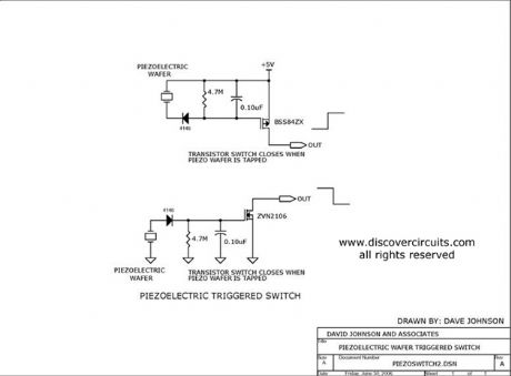
Two different switch circuits are shown. One sources current and the second sinks current. Both switches are connected to a piezoelectric wafer. When the wafer is tapped, the switches are activated.
Source: discovercircuits (View)
View full Circuit Diagram | Comments | Reading(1145)
Basement Doorbell
Published:2012/9/4 20:22:00 Author:Ecco | Keyword: Basement Doorbell

This circuit will activate a beeper in the basement, whenever the front doorbell is pressed.
Source: discovercircuits (View)
View full Circuit Diagram | Comments | Reading(866)
ANOTHER VERY LOUD PIEZO ALARM BEEPER
Published:2012/9/4 20:21:00 Author:Ecco | Keyword: ANOTHER , VERY LOUD, PIEZO , ALARM BEEPER

This is yet another beeper circuit that really draws attention. It sweeps the drive frequency slightly to produce a very annoying sound. It uses a transformer to increase the drive voltage across the piezoelectric device to more than 200 volts peak to peak. It cranks out an ear splitting 120db when measured at 12 inches.
Source: discovercircuits (View)
View full Circuit Diagram | Comments | Reading(2207)
WIDE BAND ZERO CROSS DETECTOR
Published:2012/9/4 20:18:00 Author:Ecco | Keyword: WIDE BAND , ZERO , CROSS , DETECTOR

This circuit was designed to convert a low amplitude 40KHz signal into a clean square wave signal. It will work with inputs as small as 5mv peak-to-peak or as large as 3 volts peak to peak. The input frequency can range from a few kilohertz to about 150KHz.
Source: discovercircuits (View)
View full Circuit Diagram | Comments | Reading(8130)
N-CH AND P-CH TRANSISTORS FORM PUSH-PULL DRIVER
Published:2012/9/4 20:14:00 Author:Ecco | Keyword: N-CH, P-CH , TRANSISTORS , PUSH-PULL DRIVER
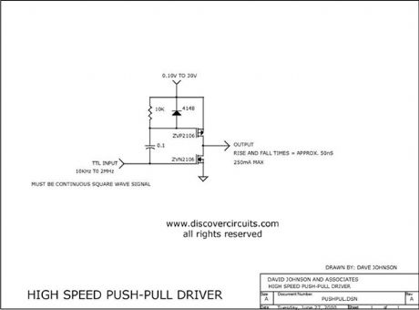
This circuit can produce high speed output signals with fast rise and full times. The unique change pump action allows the voltage of the upper P-ch device to range from millivolts to hundreds of volts. The output current is only limited by the rating of the transistors. I have used this circuit beyond 2MHz.
Source: discovercircuits (View)
View full Circuit Diagram | Comments | Reading(724)
CIRCUIT FORMS DIVIDE BY 1.5 COUNTER
Published:2012/9/4 20:13:00 Author:Ecco | Keyword: CIRCUIT FORMS DIVIDE , 1.5 COUNTER
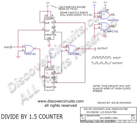
Two inexpensive ICs divide a TTL clock signal by 1.5. By following the circuit with another flip/flop, you could also generate a divide by three function.
Source: discovercircuits (View)
View full Circuit Diagram | Comments | Reading(1592)
AUDIO FREQUENCY DIGITAL NOISE GENERATOR
Published:2012/9/4 20:13:00 Author:Ecco | Keyword: AUDIO , FREQUENCY , DIGITAL , NOISE GENERATOR
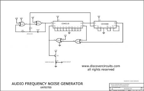
When you need to test an audio circuit with broadband noise, this circuit works great. It uses just three inexpensive C-MOS ICs that generate a series of output pulses whose widths vary randomly. I included a level control pot.
Source: discovercircuits
(View)
View full Circuit Diagram | Comments | Reading(1)
ELECTRIC FIELD DISTURBANCE MONITOR - Front End + Power Supply Circuits
Published:2012/9/4 20:11:00 Author:Ecco | Keyword: ELECTRIC, FIELD , DISTURBANCE MONITOR , - Front End + , Power Supply

This schematic is the power supply and front-end sections of the field monitor that is discussed in more detail at Electric Field Disturbance Monitor. (this link is off-site) The system can detect human and animal motion by the electric fields they disturb.
Source: discovercircuits (View)
View full Circuit Diagram | Comments | Reading(1637)
AUDIO AMP + 3KHz FILTER
Published:2012/9/4 20:10:00 Author:Ecco | Keyword: AUDIO , AMP, + 3KHz , FILTER

This circuit is the audio amp section for a complete optical transmitter. The circuit amplifies and filters the voice audio signals from an electret microphone. The circuit is described in more detail in the receiver section of Dave Johnson's Handbook of Optical Through the Air Communications.
Source: discovercircuits (View)
View full Circuit Diagram | Comments | Reading(3)
HIGH PASS ACTIVE FILTER COLLECTION
Published:2012/9/4 20:09:00 Author:Ecco | Keyword: HIGH PASS , ACTIVE , FILTER COLLECTION
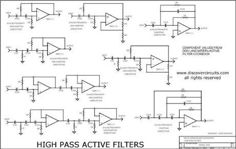
This is a collection of inverting and non-inverting active high pass filter circuits. I included one, two three, four and six pole filter circuits. You can change the component value ratios shown to achieve any frequency cut-off you may need. The circuit does not specify an operational amplifier. The circuits should be used to select the needed resistor and capacitor components for a particular frequency knee and slope.
Source: discovercircuits (View)
View full Circuit Diagram | Comments | Reading(3947)
Non-isolated Off-line AC to DC Power Supply
Published:2012/9/4 20:08:00 Author:Ecco | Keyword: Non-isolated , Off-line, AC to DC, Power Supply

Non-isolated Off-line AC to DC Power Supply
Source: discovercircuits
(View)
View full Circuit Diagram | Comments | Reading(2869)
LOW POWER 12,000 VOLT POWER SUPPLY
Published:2012/9/4 20:08:00 Author:Ecco | Keyword: LOW POWER , 12,000 VOLT , POWER SUPPLY

If you need about 12,000 volts DC for an ion generator this circuit might be the ticket. It draws power from the 120vac power line but it uses a small 6KV camera flash trigger coil. The output signal is isolated from the power line. Although the circuit can only deliver about 5uA of current it can produce dangerous shocks, so be careful.
Source: discovercircuits (View)
View full Circuit Diagram | Comments | Reading(1958)
Energy Harvesting Using a Current Transformer
Published:2012/9/4 20:07:00 Author:Ecco | Keyword: Energy Harvesting , Current Transformer
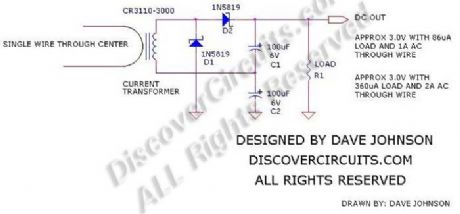
Energy harvesting is all the rage these days. With some modern electronics, information from low power sensors can be sent to a distant data collection point using a low power RF transmitter. To power these remote sensors, various energy sources can be tapped into. Machine vibration, temperature differences, ambient light and stray RF have all been used as low power energy sources. Sometimes, the sensors are located near AC power cables. Rather than making a direct connection to those cables, an AC current transformer, such as the one shown below, can be used to capture a bit of power.
Source: discovercircuits (View)
View full Circuit Diagram | Comments | Reading(1589)
Classic Plus and Minus DC Power Supply
Published:2012/9/4 4:13:00 Author:Ecco | Keyword: Classic, Plus , Minus, DC Power Supply

This is a classic example of a regulated DC power supply that produces both a positive 15v and a negative 15v from a 20vac wall adapter.
Source: discovercircuits (View)
View full Circuit Diagram | Comments | Reading(2300)
CAPS PROVIDE VOLTAGE BOOST TO SERIES REGULATOR
Published:2012/9/4 4:11:00 Author:Celina | Keyword: SERIES REGULATOR, VOLTAGE BOOST

This circuit adds some capacitors and diodes to a traditional transformer type series regulator circuit to extend the normal operating range. It can insure regulation during low line voltage conditions or it can squeeze a few more watts out of a plug-in-the-wall power adapter power supply. (View)
View full Circuit Diagram | Comments | Reading(714)
VARIABLE ISOLATED AC VOLTAGE SPANS 0VAC TO 280VAC
Published:2012/9/4 4:10:00 Author:Celina | Keyword: 80VAC, VARIABLE ISOLATED

I designed and built this circuit about 25 years ago. It came in handy for many projects that were powered from 120 VAC, 240 VAC and 277 VAC. It provides complete isolation from the power line. It uses two 1:1 isolation transformers that are wired in parallel for the140vac range and in series for the 280vac range. The selector switch also diverts power to the appropriate output socket to avoid mishaps in sending the wrong voltage to the load. My home-built unit also included an AC volt and amp meter to monitor the output. However, this circuit only indicates the AC power connections. (View)
View full Circuit Diagram | Comments | Reading(775)
18v AC to DC Power Supply
Published:2012/9/4 4:02:00 Author:Celina | Keyword: 18v , AC to DC

This is a classic linear power supply which produces a regulated 18v, rated at about 1 amp. (View)
View full Circuit Diagram | Comments | Reading(1074)
ISOLATED AC CURRENT MONITOR
Published:2012/9/4 3:59:00 Author:Ecco | Keyword: ISOLATED , AC , CURRENT , MONITOR
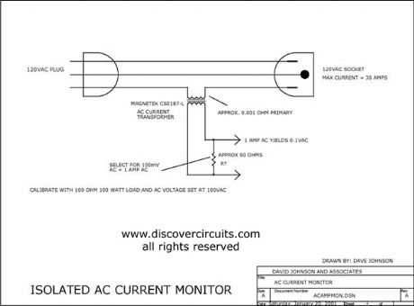
This circuit uses a small AC current transformer from Magnetek to produce an isolated voltage proportional to the AC current in the primary winding. The transformer contains a single turn primary with a low 0.001-ohm resistance. It can easily handle 30 amps of AC current and provides at least 500vac of isolation. With the components shown, the output AC voltage is scaled so 1 amp of current produces 100mv of AC voltage.
Source: discovercircuits (View)
View full Circuit Diagram | Comments | Reading(1972)
VARIABLE ISOLATED AC VOLTAGE SPANS 0VAC TO 280VAC
Published:2012/9/4 3:58:00 Author:Ecco | Keyword: VARIABLE , ISOLATED, AC VOLTAGE , SPANS , 0VAC TO 280VAC

I designed and built this circuit about 25 years ago. It came in handy for many projects that were powered from 120 VAC, 240 VAC and 277 VAC. It provides complete isolation from the power line. It uses two 1:1 isolation transformers that are wired in parallel for the140vac range and in series for the 280vac range. The selector switch also diverts power to the appropriate output socket to avoid mishaps in sending the wrong voltage to the load. My home-built unit also included an AC volt and amp meter to monitor the output. However, this circuit only indicates the AC power connections.
Source: discovercircuits (View)
View full Circuit Diagram | Comments | Reading(1554)
ISOLATED AC CURRENT MONITOR
Published:2012/9/4 3:31:00 Author:jailer

This circuit uses a small AC current transformer from Magnetek to produce an isolated voltage proportional to the AC current in the primary winding. The transformer contains a single turn primary with a low 0.001-ohm resistance. It can easily handle 30 amps of AC current and provides at least 500vac of isolation. With the components shown, the output AC voltage is scaled so 1 amp of current produces 100mv of AC voltage. (View)
View full Circuit Diagram | Comments | Reading(2)
| Pages:354/2234 At 20341342343344345346347348349350351352353354355356357358359360Under 20 |
Circuit Categories
power supply circuit
Amplifier Circuit
Basic Circuit
LED and Light Circuit
Sensor Circuit
Signal Processing
Electrical Equipment Circuit
Control Circuit
Remote Control Circuit
A/D-D/A Converter Circuit
Audio Circuit
Measuring and Test Circuit
Communication Circuit
Computer-Related Circuit
555 Circuit
Automotive Circuit
Repairing Circuit