
Circuit Diagram
Index 347
CMOS SCHMITT TRIGGER IC MAKES VCO
Published:2012/9/9 20:51:00 Author:Ecco | Keyword: CMOS, SCHMITT TRIGGER, IC, VCO
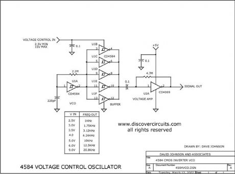
By changing the supply voltage fed to a classic 4584 Schmitt trigger type oscillator, the oscillator frequency can be changed over a range of 50:1. A 74HCU04 inverter is used at the output of the 4584 to maintain a constant TTL logic level signal.
Source: discovercircuits (View)
View full Circuit Diagram | Comments | Reading(2108)
Motion Alarm Using Piezoelectric Device
Published:2012/9/9 20:40:00 Author:Ecco | Keyword: Motion Alarm, Piezoelectric Device

An inexpensive piezoelectric device is used as a motion sensing device for this motion alarm.
Source: discovercircuits (View)
View full Circuit Diagram | Comments | Reading(1183)
Shadow Activate Motion Detector
Published:2012/9/9 20:39:00 Author:Ecco | Keyword: Shadow , Activate , Motion Detector

This circuit can sound an alarm when the shadow of a hand or arm moves over two small photo diodes.
Source: discovercircuits (View)
View full Circuit Diagram | Comments | Reading(996)
Medium Power 12v Brush Motor Speed Controller July 13, 2008
Published:2012/9/9 20:37:00 Author:Ecco | Keyword: Medium Power, 12v, Brush Motor, Speed Controller

In many applications, you would like to hold the speed of a motor constant, even as variations in the power supply voltage or mechanical load try to change its speed. In other applications, the average current to the motor needs to be limited, so the initial in-rush current when starting the motor is not too high. Also in some applications you would like to allow the motor to be in locked in a stall condition, without doing harm to the motor or the drive circuit. These two features can often be combined in a single control circuit.
Source: discovercircuits (View)
View full Circuit Diagram | Comments | Reading(969)
DC motor drive with automatic brake
Published:2012/9/9 20:36:00 Author:Ecco | Keyword: DC motor, drive , automatic brake
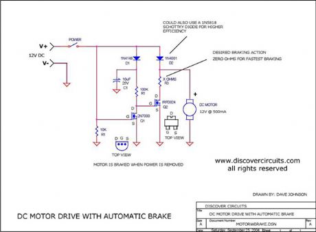
Motor Brake
Source: discovercircuits (View)
View full Circuit Diagram | Comments | Reading(992)
SOLAR POWERED PUMP MOTOR CONTROLLER
Published:2012/9/9 20:35:00 Author:Ecco | Keyword: SOLAR, POWERED , PUMP , MOTOR CONTROLLER

A Discover Circuits visitor had a problem. He needed a simple on/off controller for his solar powered water pump. His system used two 12v 50 watt solar panels wired in series. The power from the solar panels drove a submerged water pump. However, during overcast skies the pump motor did not operate properly due to the lack of power from the panel. He wanted a circuit which would turn off power to the motor during low sun conditions. The circuit below performs this function. A small 0.1? x 0.1? photodiode monitors the sunlight intensity. The current from the diode is proportional to sunlight intensity. An adjustable load resistor across the diode converts the current into a voltage and feeds the to a voltage comparator circuit. The output of the comparator drives a small n-channel MOSFET, which in turn drives a high current p-channel MOSFET, controlling power to the pump motor. When the sunlight is less than one fourth of full intensity, power to the motor is turned off.
Source: discovercircuits (View)
View full Circuit Diagram | Comments | Reading(1985)
Low Power Oscillators
Published:2012/9/9 20:34:00 Author:Ecco | Keyword: Low Power , Oscillators

This page has two unusual two-transistor oscillators. I set the component values for a low frequency application. Both circuits draw only about 1 microamp of current.
Source: discovercircuits (View)
View full Circuit Diagram | Comments | Reading(1413)
CIRCUIT PROTECTS BATTERY POLARITY REVERSAL
Published:2012/9/9 20:33:00 Author:Ecco | Keyword: PROTECTS , BATTERY , POLARITY REVERSAL

This simple circuit can protect a sensitive electronic circuit from an accidental connection of a battery with a reversed polarity. The N-channel FET connects the electronic device to the battery only when the polarity is correct. The circuit shown was designed for a device powered from a single 1.5 volts button cell battery. However, the circuit will operate with higher voltages as well.
Source: discovercircuits (View)
View full Circuit Diagram | Comments | Reading(1941)
D-FLIP/FLOP ONE SHOT CIRCUITS
Published:2012/9/9 20:32:00 Author:Ecco | Keyword: D-FLIP/FLOP, ONE SHOT CIRCUITS
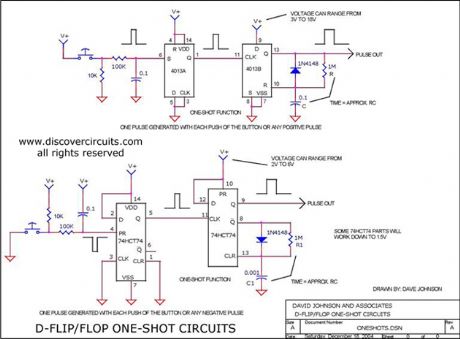
Yes you can use cheap D flip/flop logic circuits as nice one-shot pulse generators. This schematic shows how the popular CD4013 and the CD74HC74 can be used to generate pulses ranging from nanoseconds to seconds.
Source: discovercircuits (View)
View full Circuit Diagram | Comments | Reading(2786)
Delayed Pulse Generator
Published:2012/9/9 20:31:00 Author:Ecco | Keyword: Delayed , Pulse , Generator

This circuit generates a short 10ms pulse 15 minutes after a ?start? pushbutton switch is activated. (added 12/04)
Source: discovercircuits (View)
View full Circuit Diagram | Comments | Reading(0)
Water Flowing in Pipe Indicator -- July 6, 2009
Published:2012/9/9 20:30:00 Author:Ecco | Keyword: Water Flowing, in Pipe, Indicator

The vibrations associated with water flowing through a pipe are picked up by an inexpensive piezoelectric wafer. The signal from the wafer is first boosted by a micropower transistor amplifier and then fed to an ultra low power voltage comparator. When the vibration signal has sufficient amplitude, a FET transistor switch is activated. Drawing only 6uA, the whole circuit is powered by a lithium coin battery, which should power the circuit for many years.
Source: discovercircuits (View)
View full Circuit Diagram | Comments | Reading(843)
Fridge neon multi-point status indicator circuit
Published:2012/9/6 22:43:00 Author:Ecco | Keyword: Fridge neon , multi-point , status indicator
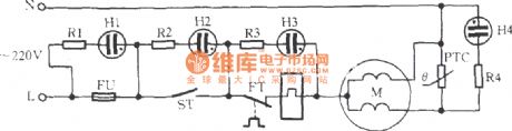
In the figure, M is the refrigerator compressor motor. H1 ~ H4 are neon lamps, R1 ~ R4 arelimiting resistors. FU is fuse, ST is the thermostat, FT is the overload protector, PTC is thestarter. Multi- point action or failure is displayed by neon, and theline is simple and convenient to identify.
(View)
View full Circuit Diagram | Comments | Reading(703)
Capacitor buck driving LED circuit 1
Published:2012/9/6 22:40:00 Author:Ecco | Keyword: Capacitor buck , driving , LED

In the circuit,SCR and R3 form the protection circuit, when the current flowing through LED current is greater than the set value, SCRturns a certain angle to distribute the circuit current, so that LED works in a constant current state to avoid LEDfrom beingdamaged due to the high-voltage transient.
(View)
View full Circuit Diagram | Comments | Reading(1261)
The manual series resistor to start three-phase motor circuit
Published:2012/9/6 22:32:00 Author:Ecco | Keyword: manual series resistor , start , three-phase motor

Operation method: you can click the start button ST, and AC contactor KMT will pull in, then the motor M connected to the startup resistor R in series will start. Until the motor speed is up to 70% of rated speed, and then clicking the run button SN again, KMN pulls in, and its main contact makes R be shorted connected and provides rated voltage for motor M, then the motor will enter the rated operating status.
(View)
View full Circuit Diagram | Comments | Reading(1063)
Water tower, pool water recycling control circuit
Published:2012/9/6 22:14:00 Author:Ecco | Keyword: Water tower , pool water , recycling control

Some places reqiure ( such as stone cutting ) high water consumption, in order to save water and reduce pollution, these place usually utilize water recycling meyhod. The used water flows into the pool, then it is pumped to the water tower. The water recycling control circuit shown in figure can realize water pump automatic control.
(View)
View full Circuit Diagram | Comments | Reading(1620)
Bidirectional thyristor power consumption brake circuit
Published:2012/9/6 22:22:00 Author:Ecco | Keyword: Bidirectional thyristor , power consumption , brake
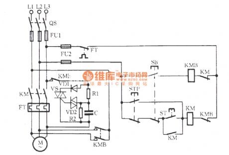
As shown in the figure, VS is the bidirectional thyristor, and its conduction angle determines the size of the braking energy; VD2 is the trigger tube, the 30V breakdown voltage enables VS reliable and stable trigger. VD1 is the rectifier diode, R2 is bleeder resistor to make the charge on the C be discharged at any time. R1, C form the phase shifting circuit to control the VS conduction angle, thereby providing an appropriate size of pulsating DC voltage for braking. C takes higher value, the braking time is longer; Conversely, the braking time is shorter. People can select appropriate capacitance of C to make brake average voltage be 85V, the brake current be 4.5 ~~ 5A, motor full load brake time be 4 to 5 seconds. KM is the main contact for the operation of the motor M, KMB is brake contactor of motor M.
(View)
View full Circuit Diagram | Comments | Reading(1761)
Bathroom door controlled switch circuit (3)
Published:2012/9/6 22:01:00 Author:Ecco | Keyword: Bathroom door , controlled switch

It uses magnetron door switch ( it is composed of permanent magnet and doorframe Reed mounted on the door ) to control the lights and exhaust fan in bathroom, it is easy to use, safe and reliable. The bathroom door controlled switch circuit consists of the power circuit and control circuit, and it is shown in the figure.
R1, R5 and R6 select 1/2W metal film resistors; R2~ R4 select 1/4W or 1/8W metal film resistors.C1 selects the polyester capacitor or CBB capacitor with pressure valuebeing more than 400V; C2 and C3 select 16 V aluminum electrolytic capacitors.VD uses 1N4007 type silicon rectifier diode.VS selects 1W, 9.1V silicon voltage diode .VT uses 2A, 400V TRIAC .VLC selects NOC 3020 optocoupler.IC uses CD4017 decimal counting / divider integrated circuit.SA uses the normally closed reed switch.
(View)
View full Circuit Diagram | Comments | Reading(732)
Bathroom door controlled switch circuit (4)
Published:2012/9/6 21:55:00 Author:Ecco | Keyword: Bathroom door , controlled, switch

The circuit is simple, easy to make without debugging, and it can be used for bathroom exhaust fan controlling. The bathroom door controlled switch circuit consists of power circuit and control circuit, and it is shown in the figure.
R selects 1/4W carbon film resistor or metal film resistor.C1 and C2 select aluminum electrolytic capacitors with voltage in 16V.VD uses 1N4001 or 1N4007 silicon rectifier diodes.UR selects 1A , 50V rectifier bridge pile.V uses C8050, S8050 or 3DG8050 silicon NPN transistor.T chooses 3W power transformer with 9V secondary voltage.K selects 4098 9V DC relay.S1 is theoriginal ventilator outlet's power switch; S2is broken (normally closed ) micro switch or button.
(View)
View full Circuit Diagram | Comments | Reading(828)
Bathroom door controlled switch circuit (1)
Published:2012/9/6 21:42:00 Author:Ecco | Keyword: Bathroom door , controlled switch

It uses magnetron six switch to control lights and exhaust fan in the bathroom, and it has strong practical applicability. The bathroom six control switch circuit is composed of the power circuit and control circuit, and it is shown in Fig.R1 ~ R6 select 1/4W carbon film resistors.RP uses small membrane potentiometer ( it is used to adjust the delay time of the exhaust fan ).C1, C2 and C4 select aluminum electrolytic capacitors with voltage in 16V; C3, C5 ~ C7 choose polyester capacitors.VD1 ~ VD6 choose 1N4007 silicon rectifier diodes.V1 and V2 select S9013 or S8050 silicon NPN transistors.VT1 and VT2 selects Triacs with current in 3A and voltage being400V or more.ICl uses LM7812 three-terminal integrated voltage regulator; IC2 uses CD4027 digital integrated circuit; IC3 uses NE555 time-base integrated circuit.T uses 3 ~ 5W power transformer with 12Vsecondary voltage.EL can choose 15 ~ 60 W lamp.
(View)
View full Circuit Diagram | Comments | Reading(965)
Inverter circuit ( three - phase bridge circuit )
Published:2012/9/6 21:28:00 Author:Ecco | Keyword: Inverter , three - phase bridge
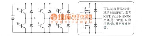
It can be a bipolar transistor, or MOSFET, or IGBT, NPN or PNP, N- channel or P-channel, and even complementary.
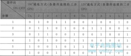
Basic switching sequence of the three - phase inverter is shown asfollowing (if the order is reversed , then the motoris reversed, too. Theswitch combination with the DC converter and invertercan adjust the voltage).
(View)
View full Circuit Diagram | Comments | Reading(1665)
| Pages:347/2234 At 20341342343344345346347348349350351352353354355356357358359360Under 20 |
Circuit Categories
power supply circuit
Amplifier Circuit
Basic Circuit
LED and Light Circuit
Sensor Circuit
Signal Processing
Electrical Equipment Circuit
Control Circuit
Remote Control Circuit
A/D-D/A Converter Circuit
Audio Circuit
Measuring and Test Circuit
Communication Circuit
Computer-Related Circuit
555 Circuit
Automotive Circuit
Repairing Circuit