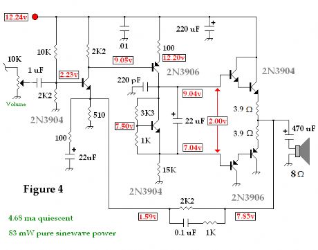
Circuit Diagram
Index 237
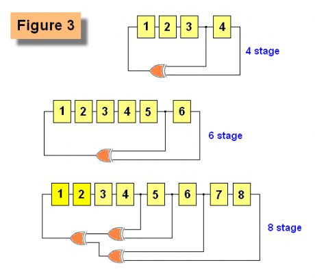
Pseudo-Random Number Generator 3
Published:2012/12/17 20:25:00 Author:muriel | Keyword: Pseudo-Random, Number Generator 2
View full Circuit Diagram | Comments | Reading(1797)
Pseudo-Random Number Generator 2
Published:2012/12/17 20:24:00 Author:muriel | Keyword: Pseudo-Random , Number Generator 2
View full Circuit Diagram | Comments | Reading(1453)
Pseudo-Random Number Generator
Published:2012/12/17 20:24:00 Author:muriel | Keyword: Pseudo-Random, Number Generator
View full Circuit Diagram | Comments | Reading(1321)
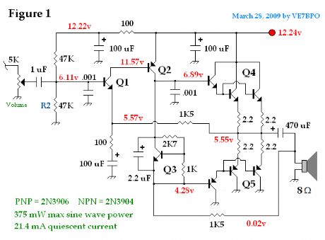
Low Power Popcorn Audio Power Amp 5
Published:2012/12/17 20:22:00 Author:muriel | Keyword: Low Power, Popcorn Audio, Power Amp 5
View full Circuit Diagram | Comments | Reading(643)
Low Power Popcorn Audio Power Amp 4
Published:2012/12/17 20:21:00 Author:muriel | Keyword: Low Power, Popcorn Audio, Power Amp 4
View full Circuit Diagram | Comments | Reading(601)
Low Power Popcorn Audio Power Amp 3
Published:2012/12/17 20:21:00 Author:muriel | Keyword: Low Power , Popcorn Audio, Power Amp 3
View full Circuit Diagram | Comments | Reading(666)
Low Power Popcorn Audio Power Amp 2
Published:2012/12/17 20:20:00 Author:muriel | Keyword: Low Power , Popcorn Audio , Power Amp
View full Circuit Diagram | Comments | Reading(944)
Low Power Popcorn Audio Power Amp
Published:2012/12/17 20:20:00 Author:muriel | Keyword: Low Power, Popcorn Audio , Power Amp
View full Circuit Diagram | Comments | Reading(947)
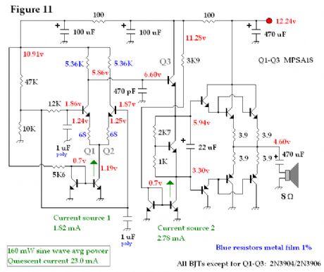
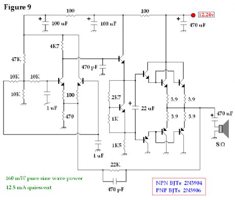
Discrete BJT, Low Power Audio Power Amp 10
Published:2012/12/17 20:16:00 Author:muriel | Keyword: Discrete BJT, Low Power, Audio, Power Amp 10
View full Circuit Diagram | Comments | Reading(1408)
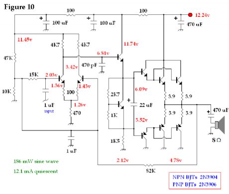
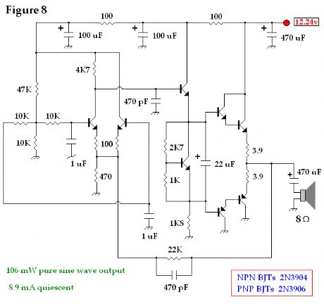
Discrete BJT, Low Power Audio Power Amp 9
Published:2012/12/17 20:16:00 Author:muriel | Keyword: Discrete BJT, Low Power, Audio, Power Amp 9
View full Circuit Diagram | Comments | Reading(985)
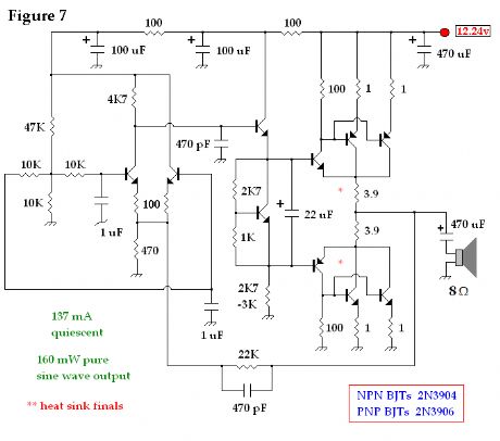
Discrete BJT, Low Power Audio Power Amp 8
Published:2012/12/17 20:15:00 Author:muriel | Keyword: Discrete BJT, Low Power , Audio, Power Amp
View full Circuit Diagram | Comments | Reading(733)
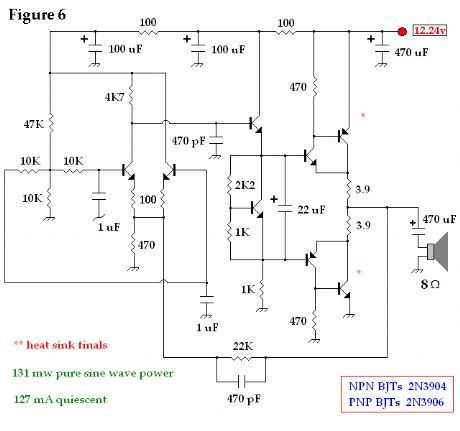
Discrete BJT, Low Power Audio Power Amp 7
Published:2012/12/17 20:15:00 Author:muriel | Keyword: Discrete BJT, Low Power , Audio , Power Amp 7
View full Circuit Diagram | Comments | Reading(1096)
Discrete BJT, Low Power Audio Power Amp 6
Published:2012/12/17 20:14:00 Author:muriel | Keyword: Discrete BJT, Low Power, Audio, Power Amp
View full Circuit Diagram | Comments | Reading(1507)
Discrete BJT, Low Power Audio Power Amp 5
Published:2012/12/17 20:14:00 Author:muriel | Keyword: Discrete BJT, Low Power, Audio , Power Amp
View full Circuit Diagram | Comments | Reading(1957)
Four-way Kala 0K lighting rendering circuit (HL3034)
Published:2012/12/17 3:10:00 Author:Ecco | Keyword: Four-way , Kala 0K , lighting rendering
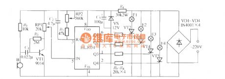
In the Figure, B is the electret condenser microphone which can pick up the the sonic signal and output corresponding electrical signals, then it is amplified by VT1 and sent to Manifold HL3034 ⑤ feet by RP1, and it can control internal voltage controlled oscillator VCO after being amplified, the oscillation frequency changes with audio signal strength. Therefore, changing Q1 ~ Q4 output pulse conversion rate can make the four groups lantern E1 ~ E4 cycle rate change with the strength of the sound waves. Adjusting the RP1 can change the voice sensitivity Lantern circulation rate of the circuit.
(View)
View full Circuit Diagram | Comments | Reading(1191)
The homemade simple emergency light circuit diagram
Published:2012/12/17 3:34:00 Author:Ecco | Keyword: homemade, simple, emergency light
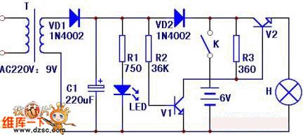
The circuit is shown as the figure, the 220V mains is rectified through transformer T, Buck by VD1 to obtain approximately 9V DC voltage on the capacitor C1. This voltage charges for battery all the way through VD2, and resistor R2 provides the base bias for V1 until saturated conduction, then V2 is turned off, bulb H does not shine.
(View)
View full Circuit Diagram | Comments | Reading(2220)
Scanning oscillator circuit diagram
Published:2012/12/17 3:42:00 Author:Ecco | Keyword: Scanning oscillator

This circuit is composed of RC Wien bridge oscillator and voltage controlled resistor, wherein the Wien bridge circuit is available for RC circuit with a selected frequency, and A1 magnification is about three times, loop gain is 1. The output of A2 is half wave rectified by VD2, then it is comparing with the reference current generated by VD4 to make integrating, thereby controlling the VT1's gate voltage and changing the resistance between the drain - source.
(View)
View full Circuit Diagram | Comments | Reading(1015)
Electronic imitation sound pest quitter circuit diagram
Published:2012/12/17 2:50:00 Author:Ecco | Keyword: Electronic , imitation sound , pest quitter

R2 is a 10k Ω fine-tuning resistor; R3 is a 130kΩ fine tuning resistor; R3 is a 200Ω resistor; R5 is a 510k Ω fine-tuning resistor; C1 uses 330u/16V electrolytic capacitor; C2, C3 are 0.01u polyester capacitors; C4 is a 680P porcelain capacitor; C5 uses 1u/16V 1 Electrolytic Capacitor; C6, C7 are 10u/16V Electrolytic Capacitors; VD1 and VD2 are IN4148 switching diodes.
(View)
View full Circuit Diagram | Comments | Reading(1465)
Isolation and directly driving CW1840 driver MOS tube circuit diagram
Published:2012/12/17 2:36:00 Author:Ecco | Keyword: Isolation , directly driving , driver, MOS tube
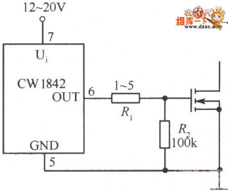
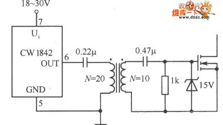
Isolation and directly driving CW1840 driver MOS tube circuit diagram is shown as the figure.
(View)
View full Circuit Diagram | Comments | Reading(608)
Discrete BJT, Low Power Audio Power Amp 4
Published:2012/12/16 21:17:00 Author:muriel | Keyword: Discrete BJT, Low Power, Audio Power Amp
View full Circuit Diagram | Comments | Reading(885)
| Pages:237/2234 At 20221222223224225226227228229230231232233234235236237238239240Under 20 |
Circuit Categories
power supply circuit
Amplifier Circuit
Basic Circuit
LED and Light Circuit
Sensor Circuit
Signal Processing
Electrical Equipment Circuit
Control Circuit
Remote Control Circuit
A/D-D/A Converter Circuit
Audio Circuit
Measuring and Test Circuit
Communication Circuit
Computer-Related Circuit
555 Circuit
Automotive Circuit
Repairing Circuit
