
Circuit Diagram
Index 232
Automotive Voltage Indicator
Published:2012/12/21 21:24:00 Author:muriel | Keyword: Automotive , Voltage Indicator

View full Circuit Diagram | Comments | Reading(632)
Power Flasher
Published:2012/12/21 21:24:00 Author:muriel | Keyword: Power Flasher

View full Circuit Diagram | Comments | Reading(911)
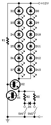
Sequential Brake/Turn Lights
Published:2012/12/21 21:23:00 Author:muriel | Keyword: Sequential , Brake/Turn , Lights

View full Circuit Diagram | Comments | Reading(1344)
LED driven tail/brake Light Cluster
Published:2012/12/21 21:23:00 Author:muriel | Keyword: LED driven, tail/brake Light , Cluster
View full Circuit Diagram | Comments | Reading(1136)
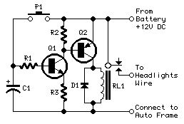
Headlights Timer
Published:2012/12/21 21:22:00 Author:muriel | Keyword: Headlights Timer
View full Circuit Diagram | Comments | Reading(624)
8 ~ 12MHz voltage controlled oscillator circuit diagram with stable output amplitude
Published:2012/12/21 1:44:00 Author:Ecco | Keyword: 8 ~ 12MHz , voltage controlled oscillator , stable output amplitude
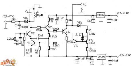
In the circuit, VT2 controls the collector current of VT1, therefore, the oscillation amplitude of VT1 is very stable. VT4 output signal is converted into a DC signal by VD2 detector, here is the automatic gain controlling state, so that the DC voltage is kept constant. RP1's midpoint voltage is - 0.6V, and the current holding in R1 and R2 is equal, thereby controlling the output amplitude constant value. Oscillation frequency is decided by L1, C2, varactor diode VD1 and distributed capacitor. Uo output voltage is 2V, the frequency is 8 ~ 12MHz signal.
(View)
View full Circuit Diagram | Comments | Reading(1598)
Low-power high-impedance DC amplifier circuit diagram with adjustable gain
Published:2012/12/21 1:29:00 Author:Ecco | Keyword: Low-power, high-impedance , DC amplifier , adjustable gain

Low-power high-impedance DC amplifier circuit diagram with adjustable gain is shown as the figure.
(View)
View full Circuit Diagram | Comments | Reading(1402)
Low distortion Wien bridge oscillator circuit diagram
Published:2012/12/21 3:08:00 Author:Ecco | Keyword: Low distortion , Wien bridge, oscillator

The oscillation principle is that when the loop phase shift amount is an integer multiple of 0 ° or 360 °, the loop gain is greater than 1, the circuit starts oscillation. If the oscillation is increased, the circuit will be saturated, therefore it needs an amplitude stabilization circuit. In the circuit, the amplitude stabilization circuit uses a junction FET (VT1) drain - source resistor to connect with R1 in series to make R2 / 2 = 4.7kΩ / 2 = 2.35kΩ.
(View)
View full Circuit Diagram | Comments | Reading(2282)
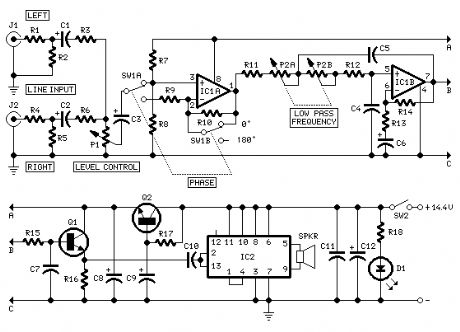
Stereo amplifier circuit
Published:2012/12/21 1:28:00 Author:Ecco | Keyword: Stereo amplifier

The circuit shown in Figure 19.27 uses low-power preamplifier TDA3310 and TDA2030 power amplifier integrated circuit. The former is used for the dual-channel UE2 and UE2 input and frequency correction, the latter is used for power amplification. External power supply voltage is ± 14V, output current is high, and it has the features of excellent short-circuit protection, overheating protection and automatic limit power consumption, so it can be used in high-quality stereo system.
(View)
View full Circuit Diagram | Comments | Reading(2147)
The R3 trigger circuit with adjustable trigger level
Published:2012/12/21 1:18:00 Author:Ecco | Keyword: R3 trigger , adjustable trigger level

The circuit has two input terminals, i.e. the triggered terminal ( pin 8 ) and reset terminal ( pin 12 ). The trigger level is adjusted by potentiometer RP (10kΩ). Figure b illustrates the pulse waveform. At time t1, the input voltage UE = U8 is lower than the setting trigger voltage U6 = U7, and the reset input remains high ( + U.S. ) level, the pin 14 outputs high level to block the output terminal (pin 2), then U2 is in low level. Until UE = U8 achieve the setting trigger voltage U6 = U7, output voltage U2 only changes to high from low level.
(View)
View full Circuit Diagram | Comments | Reading(606)
Park-Aid Modification
Published:2012/12/20 21:17:00 Author:muriel | Keyword: Park-Aid Modification

View full Circuit Diagram | Comments | Reading(625)
Park-Aid
Published:2012/12/20 21:16:00 Author:muriel | Keyword: Park-Aid

View full Circuit Diagram | Comments | Reading(165)
Speed-limit Alert
Published:2012/12/20 21:16:00 Author:muriel | Keyword: Speed-limit Alert

View full Circuit Diagram | Comments | Reading(746)
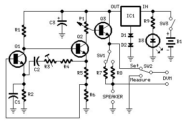
Loudspeaker Impedance Meter
Published:2012/12/20 21:12:00 Author:muriel | Keyword: Loudspeaker Impedance Meter
View full Circuit Diagram | Comments | Reading(1104)
Portable Phono Preamplifier
Published:2012/12/20 21:11:00 Author:muriel | Keyword: Portable Phono , Preamplifier

View full Circuit Diagram | Comments | Reading(619)
Car Subwoofer Driver
Published:2012/12/20 21:11:00 Author:muriel | Keyword: Car Subwoofer Driver
View full Circuit Diagram | Comments | Reading(644)
Headphone Amplifier Module
Published:2012/12/20 21:10:00 Author:muriel | Keyword: Headphone Amplifier Module

View full Circuit Diagram | Comments | Reading(831)
Mixer Module
Published:2012/12/20 21:09:00 Author:muriel | Keyword: Mixer Module
View full Circuit Diagram | Comments | Reading(1801)
Microphone Amplifier Module
Published:2012/12/20 21:09:00 Author:muriel | Keyword: Microphone Amplifier Module

View full Circuit Diagram | Comments | Reading(590)
Magnetic Pick-up Amplifier Module
Published:2012/12/20 21:08:00 Author:muriel | Keyword: Magnetic Pick-up, Amplifier Module

View full Circuit Diagram | Comments | Reading(911)
| Pages:232/2234 At 20221222223224225226227228229230231232233234235236237238239240Under 20 |
Circuit Categories
power supply circuit
Amplifier Circuit
Basic Circuit
LED and Light Circuit
Sensor Circuit
Signal Processing
Electrical Equipment Circuit
Control Circuit
Remote Control Circuit
A/D-D/A Converter Circuit
Audio Circuit
Measuring and Test Circuit
Communication Circuit
Computer-Related Circuit
555 Circuit
Automotive Circuit
Repairing Circuit