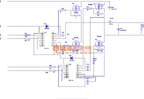
Circuit Diagram
Index 2008
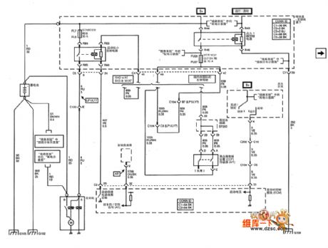
Shanghai GM Cadillac CTS car 3.6 L motor circuit diagram(2)
Published:2011/4/26 1:40:00 Author:Nicole | Keyword: GM, Cadillac, CTS car, 3.6 L motor
View full Circuit Diagram | Comments | Reading(557)
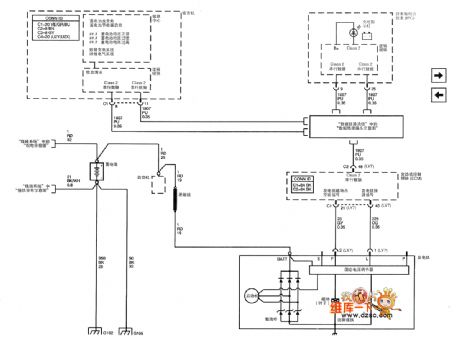
Shanghai GM Cadillac CTS car 3.6 L motor circuit diagram(1)
Published:2011/4/26 1:41:00 Author:Nicole | Keyword: GM, Cadillac, CTS car, 3.6 L motor
View full Circuit Diagram | Comments | Reading(413)
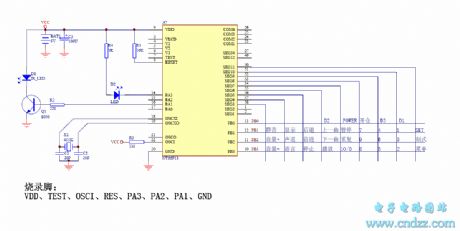
100 in 1 Multi-function VCD remote control circuit(compatible with co-RM-220 and NT66P13)
Published:2011/4/20 5:03:00 Author:Rebekka | Keyword: VCD remote control
View full Circuit Diagram | Comments | Reading(664)
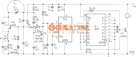
Ultra-small 400 meters wireless remote control circuit diagram
Published:2011/4/24 10:03:00 Author:Rebekka | Keyword: wireless remote control
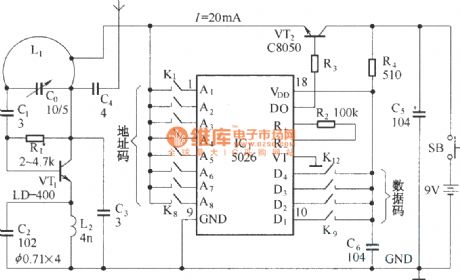
Transmitter circuit:
Receiver circuit:
Ultra-small wireless remote control use 400-meter digital encoder / decoder VD5026/VD5027 as the core and use emission-specific transistor LD-400, the remote distance is far, its operation stable and reliable. (View)
View full Circuit Diagram | Comments | Reading(2556)
Using DTMF encoding and decoding wireless calling implement circuit diagram
Published:2011/4/24 10:59:00 Author:Rebekka | Keyword: DTMF , encoding and decoding , wireless calling implement


The wireless calling implement is composed of calling implement and the host. The two parts use DTMF encoder pulse to realise communication. Different calling implement has different codes only, the circuits are all the same. The calling implement is shown in figure 1. IC2 is the DTMF encoding specific integrated circuit (telephone dial tone can also be integrated circuits), which has four southbound R1 ~ R4, C1 ~ C4 line of four columns, external standard 4 × 4 matrix keyboard. It produces 16 different encoding. When any key is pressed, a row line and a column line are connected. Then the output pin corresponding to the end TONE tone pulses. It uses optocoupler number keys as the icon to connect to 1 # key. IC3 serial data of the long-wave radio transmitter module, which uses 150kHz carrier frequency, a strong anti-interference ability. IC2 pin dual audio pulses emitted modulated carrier out by the antenna.
(View)
View full Circuit Diagram | Comments | Reading(2169)
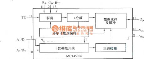
The internal structure of MCl45026
Published:2011/4/20 3:42:00 Author:Rebekka | Keyword: internal structure
View full Circuit Diagram | Comments | Reading(426)
MCl45030 internal structure circuit diagram
Published:2011/4/20 3:36:00 Author:Rebekka | Keyword: internal structure
View full Circuit Diagram | Comments | Reading(437)
500 w Light modulation circuit diagram
Published:2011/4/20 10:00:00 Author:Rebekka | Keyword: Light modulation

When the circuit is connected to the hi-fi equipment or at both ends of the electronic instruments speaker, the audio level can be modulated to 500W lamp by proportion. Using 3 appropriate sets of audio filters and 3 different color light Union microscopy to access to color music stage lighting effects. (View)
View full Circuit Diagram | Comments | Reading(1539)
±5--±20V slave tracking stabilized voltage supply minus side driven pulley plus side
Published:2011/4/2 1:55:00 Author:may | Keyword: ±5--±20V, slave tracking, stabilized voltage supply, minus side driven pulley plus side
View full Circuit Diagram | Comments | Reading(794)
Touch-type anti-theft alarm circuit
Published:2011/4/24 9:38:00 Author:Christina | Keyword: Touch-type, anti-theft alarm
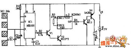
The touch-type anti-theft alarm can be used in wide range of applications such as the burglar alarm and the alarm of dangerous touch.etc. This alarm can automatic alarm and can automatic stop at the scheduled time.
As the figure showns. IC1 is the time-base integrated circuit NE555, the monostable trigger is composed of the IC1 and R1、C1、C2、C3. When no one touch the metal M1 to Mn, the circuit is stable, pin-3 of IC1 outputs the low-level signal, alarm circuit does not work. If anyone touch any piece of metal M1 to Mn, EMF of human body gives a negative pulse to pin-2 of IC1, the monostable circuit gets into the temporary-steady-state, pin-3 of IC1 become the high-level signal. This high-level signal makes the transistor V1 connect, so V2 also connect too, audio integrated circuits IC2 enters the working state. (View)
View full Circuit Diagram | Comments | Reading(888)
Power Disconnection Alarm Circuit
Published:2011/4/24 8:54:00 Author:Christina | Keyword: Power Disconnection, Alarm
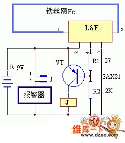
The Power Disconnection Alarm Circuit is as shown:
(View)
View full Circuit Diagram | Comments | Reading(434)
High power switching power supply circuit diagram with reliable performance
Published:2011/4/20 20:13:00 Author:May | Keyword: High power, switching power supply, reliable performance
View full Circuit Diagram | Comments | Reading(3133)
Electronic controlled fishing device
Published:2011/4/25 2:55:00 Author:May | Keyword: Electronic controlled, fishing device
View full Circuit Diagram | Comments | Reading(2496)
Latest practical 5W switching power supply circuit
Published:2011/4/20 20:23:00 Author:May | Keyword: Latest, practical, 5W, switching power supply
View full Circuit Diagram | Comments | Reading(3142)
UPS circuit diagram
Published:2011/4/25 2:48:00 Author:May | Keyword: UPS
View full Circuit Diagram | Comments | Reading(6610)
Super-audio frequency induction heating power supply
Published:2011/4/25 2:43:00 Author:May | Keyword: Super-audio frequency induction, heating power supply
View full Circuit Diagram | Comments | Reading(1751)
Fish trap 2
Published:2011/4/25 2:42:00 Author:May | Keyword: Fish trap 2
View full Circuit Diagram | Comments | Reading(1004)
Fish trap
Published:2011/4/25 2:41:00 Author:May | Keyword: Fish trap
View full Circuit Diagram | Comments | Reading(839)
Single-ended forward transform isolation type switching regulated power supply circuit produced by Cwl524A
Published:2011/4/22 4:10:00 Author:May | Keyword: Single-ended, forward transform isolation type, switching regulated power supply
View full Circuit Diagram | Comments | Reading(686)
Single-ended fly back switching regulated power supply circuit composed of CW1524
Published:2011/4/22 6:47:00 Author:May | Keyword: Single-ended, fly back, switching, regulated power supply
View full Circuit Diagram | Comments | Reading(580)
| Pages:2008/2234 At 2020012002200320042005200620072008200920102011201220132014201520162017201820192020Under 20 |
Circuit Categories
power supply circuit
Amplifier Circuit
Basic Circuit
LED and Light Circuit
Sensor Circuit
Signal Processing
Electrical Equipment Circuit
Control Circuit
Remote Control Circuit
A/D-D/A Converter Circuit
Audio Circuit
Measuring and Test Circuit
Communication Circuit
Computer-Related Circuit
555 Circuit
Automotive Circuit
Repairing Circuit
