
Circuit Diagram
Index 2018
The XC4003 minimum system circuit
Published:2011/4/25 1:46:00 Author:Ecco | Keyword: minimum system

View full Circuit Diagram | Comments | Reading(564)
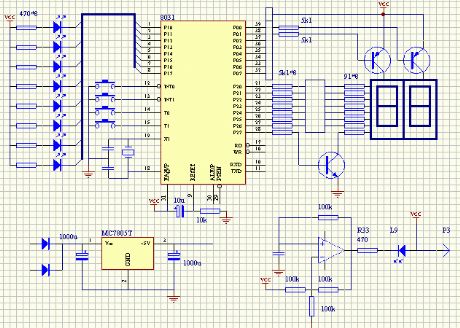
Microcontroller test board circuit 4
Published:2011/4/25 1:45:00 Author:Ecco | Keyword: Microcontroller , test board

View full Circuit Diagram | Comments | Reading(545)
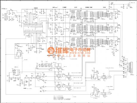
Microcontroller test board circuit 3
Published:2011/4/25 1:45:00 Author:Ecco | Keyword: Microcontroller , test board

View full Circuit Diagram | Comments | Reading(1058)
Motor vehicle steering flasher 10
Published:2011/4/21 21:38:00 Author:Ecco | Keyword: Motor vehicle , steering flasher

The working principle
The motor vehicle steering flasher is composed of capacitor C, the relay K, diode VD and resistors R, it is shown in Figure 7-19.
When the turn signal switch S is placed in L (or R position), C begins charging, and the left turn signal HLl (or right turn signal HL2) is lit. With the gradually increasing voltage of C, HLl (or HL2) light fades, when the voltage of C reaches the pull-in voltage of K, K pulls in, and its normally open contact is connected, at this time , the brightness of HLl (or HL2) is largest. Then C discharges through K, when the voltage of C voltage declines down to the releasing voltage of K, K releases, HLl (or HL2) is off. When C starts charging, HLl (or HL2) is lit again, and the circuit repeats the process.
Adjusting the resistance of R can change the note selection of turn signal flash rate.
R uses 1/2W metal film resistors.
C uses electrolytic capacitor with voltage in 35V.
VD selects 1N4001 or 1N4007 silicon rectifier diodes.
K uses 24V or 12V DC relay with the contact current capacity greater than IOA.
(View)
View full Circuit Diagram | Comments | Reading(941)
Motor vehicle steering flasher 9
Published:2011/4/21 21:21:00 Author:Ecco | Keyword: Motor vehicle, steering flasher

The motor vehicle steering flasher described in the example uses discrete components, and it has the features of low cost and easy to produce, stable performance, it can be used for motorcycle or car.
The working principle
The motor vehicle steering flasheris composed ofthe flash circuit resistors Rl-R3, capacitor Cl, C2, the transistor V, diode VD and relays K, it is shown in Figure 7-18.
Whenturning signal switch S (in the center), V does not work, K isin the releasing state, HLland HL2are notflashing.
Component selection
Rl uses 2w insurance resistors;
R2 and R3 select 1/4W metal film resistor or carbon film resistors.
Cl uses electrolytic capacitor with voltage in 16V; C2 uses polyester capacitor or CBB capacitor.
V uses S8550 silicon PNP transistor.
VD uses IN4007 silicon rectifier diode.
K selects 4098 DC relay.
(View)
View full Circuit Diagram | Comments | Reading(446)
Computer controlling home appliances switch (1)
Published:2011/4/25 1:39:00 Author:Ecco | Keyword: Computer , controlling, home appliances, switch


View full Circuit Diagram | Comments | Reading(564)
TV signal turning VGA signal circuit diagram
Published:2011/4/25 1:36:00 Author:Ecco | Keyword: TV signal , turning , VGA signal
View full Circuit Diagram | Comments | Reading(1567)
A simple 485 card circuit diagram
Published:2011/4/25 1:22:00 Author:Ecco | Keyword: simple, 485 , card

View full Circuit Diagram | Comments | Reading(436)
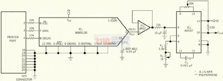
Programmable frequency generator circuit made by printer port
Published:2011/4/25 1:24:00 Author:Ecco | Keyword: Programmable , frequency generator , printer , port
View full Circuit Diagram | Comments | Reading(596)
Usb mouse circuit diagram
Published:2011/4/25 1:33:00 Author:Ecco | Keyword: Usb mouse

View full Circuit Diagram | Comments | Reading(3174)
AMD462 CPU circuit diagram
Published:2011/4/25 1:29:00 Author:Ecco | Keyword: CPU

View full Circuit Diagram | Comments | Reading(539)
Motor vehicle steering flasher 8
Published:2011/4/21 21:08:00 Author:Ecco | Keyword: Motor vehicle , steering flasher

The working principle
The motor vehicle steering flasher is composed of pulse generator and electronic switching circuit, it is shown in Figure 7-17.
Pulse generator circuit consists of NAND gate integrated circuit IC (Dl-D4), voltage regulator diode VS, resistors Rl, M, M, R5 and capacitors Cl, C2.
Electronic switching circuit consists of resistors R3, R6-RlO and transistors Vl-V3.
Sl is a vehicle turn signal switch, S2 is the door flashes light switch. HLl is the left turn signal, H is the right turn signal, HL3 is flashing lights.
+ L2V voltage is limited by R5, filtered by C2 and regulated by VS to provide IC +9 V voltage.
Component selection
Rl-R4, R6, R7 and RlO use 1/4W carbon film resistor or metal film resistors; R5 and R8 select 1/2W metal film resistors; R9 uses 5-lOW insurance resistor.
Cl and C2 chose monolithic capacitors or polyester capacitors.
VS selects lW, 9V silicon voltage-regulator diode.
Vl uses S9013 or S8050 silicon NPN transistor; V2 use 5OV silicon PNP transistors with the current higher than 5A, for example 3CA8B, BD246A or 2SA807,etc.; V3 chooses 5OV, 2A silicon PNP transistors, for example 2SAl213, 3CA4, 3CA6,etc.
IC uses CD401l or CC401l, MCl4011 NAND gate integrated circuits.
S2 chooses single pole switch with the current of contacts being over 5A.
(View)
View full Circuit Diagram | Comments | Reading(504)
Motor vehicle steering flasher 7
Published:2011/4/21 20:39:00 Author:Ecco | Keyword: Motor vehicle , steering , flasher

(View)
View full Circuit Diagram | Comments | Reading(958)
HY5PS121621BFP address / control end parallel terminal circuit diagram
Published:2011/4/24 22:34:00 Author:May | Keyword: address / control, end parallel terminal

View full Circuit Diagram | Comments | Reading(417)
Automatic regulated voltage inverter circuit
Published:2011/4/24 22:26:00 Author:May | Keyword: Automatic regulated voltage, inverter

View full Circuit Diagram | Comments | Reading(546)
Automatic transceiver conversion RS-485 interface circuit and its test circuit diagram
Published:2011/4/24 22:25:00 Author:May | Keyword: Automatic transceiver conversion, RS-485, interface, test circuit

View full Circuit Diagram | Comments | Reading(706)
Usb turning 232 circuit
Published:2011/4/24 21:21:00 Author:Ecco | Keyword: Usb , turning , 232

View full Circuit Diagram | Comments | Reading(439)
USB turning serial circuit diagram
Published:2011/4/24 21:44:00 Author:Ecco | Keyword: USB, turning, serial

View full Circuit Diagram | Comments | Reading(473)
Zastava CA7200E3(L) type air condition system circuit diagram
Published:2011/4/24 21:30:00 Author:muriel | Keyword: Zastava, air condition system

Zastava CA7200E3(L) type air condition system circuit diagram is as shown
(View)
View full Circuit Diagram | Comments | Reading(418)
Zastava CA7200E3(L) type power supply, starting and ignition system circuit diagram
Published:2011/4/24 21:32:00 Author:muriel | Keyword: Zastava , power supply, starting and ignition system

Zastava CA7200E3(L) type power supply, starting and ignition system circuit diagram
(View)
View full Circuit Diagram | Comments | Reading(427)
| Pages:2018/2234 At 2020012002200320042005200620072008200920102011201220132014201520162017201820192020Under 20 |
Circuit Categories
power supply circuit
Amplifier Circuit
Basic Circuit
LED and Light Circuit
Sensor Circuit
Signal Processing
Electrical Equipment Circuit
Control Circuit
Remote Control Circuit
A/D-D/A Converter Circuit
Audio Circuit
Measuring and Test Circuit
Communication Circuit
Computer-Related Circuit
555 Circuit
Automotive Circuit
Repairing Circuit