Circuit Diagram
Index 1867
Lavatory automatic flusher 2
Published:2011/5/17 1:24:00 Author:Nicole | Keyword: Lavatory, flusher

The circuit work theory
This lavatory automatic flusher circuit is composed of power supply circuit, infrared sensor signal amplifier circuit, delay amplifier circuit, trigger control circuit and control implement circuit, the circuit is shown in the figure 9-130.
The power supply circuit is made of capacitors C1-C6, resistors R1, R2, diode VD1, three terminal regulator integrated circuit IC1 and voltage stabilizing diode VS.
The infrared sensor signal amplifier circuit consists of pyroelectric infrared sensor integrated circuit IC2, operational amplifier integrated circuit IC3(Nl-N4)internal N1, N2, resistors R3-RlO and capacitors C7-C12.
(View)
View full Circuit Diagram | Comments | Reading(655)
Lavatory automatic flusher 3
Published:2011/5/17 1:33:00 Author:Nicole | Keyword: Lavatory, flusher

The circuit work theory
This lavatory automatic flusher circuit is composed of power supply circuit, infrared transmitting circuit, infrared receiving process circuit, delay amplifier circuit and control implement circuit, the circuit is shown in the figure 9-131.
The power supply circuit is made of power switch S1, power transformer T, bridge rectifier UR, filter capacitors C2, Cll、Cl2, resistors R4, R13, R14, voltage stabilizing diodes VS1, VS2 and power indication LED VL2.
The infrared transmitting circuit consists of infrared LED VL1, resistors R1-R3, potentiometer RP1, capacitor C1 and time base integrated circuit IC1. IC1 and R1-R3 form multivibrator.
(View)
View full Circuit Diagram | Comments | Reading(534)
Motor electronic governor controller 2
Published:2011/5/17 1:53:00 Author:Nicole | Keyword: motor, electronic governor, controller

The circuit work theory
This motor electronic governor controller circuit is composed of power supply circuit, zero passage detection circuit and power regulating circuit, the circuit is shown in the figure 8-29.
The power supply circuit is made of power transformer T, rectifier diodes VD1, VD2 and filter capacitor C.
The zero passage detection circuit consists of diodes VD3, VD4, resistor R1 and operational amplifier integrated circuit IC1.
The power regulating circuit is composed of counter/distributor integrated circuit IC2, power adjustment switch S, diodes VD5, VD6, resistors R2, R3, transistor V and SCR VT.
(View)
View full Circuit Diagram | Comments | Reading(836)
BA3404F-the integrated preamplifier circuit of self-reversal reproducing
Published:2011/5/15 5:22:00 Author:Borg | Keyword: preamplifier circuit, self-reversal


BA3404F is an integrated circuit of low-voltage self-reversal reproducing preamplifer and frequency compensation.
1.the internal circuit and pin functions of BA3404FBA3404F contains two lines of balanced preamplifier circuits, tap pros and cons input shifting e-switch circuit and LED drive and bias circuits,etc.
2.main parameters of BA3404
(View)
View full Circuit Diagram | Comments | Reading(817)
Motor electronic governor controller 3
Published:2011/5/17 2:09:00 Author:Nicole | Keyword: motor, electronic governor, controller

The circuit work theory
This motor electronic governor controller circuit is composed of power supply circuit, counter and optical control pulse width modulation circuit, the circuit is shown in the figure 8-60.
The power supply circuit is made of switch S1, depressurization capacitor C1, resistor R1, rectifier diodes VD1, VD2, steady voltage diode VS and filter capacitors C2, C3.
The optical control pulse width modulation circuit consists of resistors R4-R9, diodes VD3-VD8, LED VL, TRIAC VT, bidirectional trigger diode VD, light dependent resistor RG and resistor R10, capacitors C5.
(View)
View full Circuit Diagram | Comments | Reading(1706)
Electric oven control circuit with the AIRPAX67F temperature switch
Published:2011/5/13 1:20:00 Author:TaoXi | Keyword: Electric oven, control circuit, temperature switch

Related components PDF download:
VT66A
The circuit is as shown, it is composed of the temperature switch circuit, the stereo sound circuit and the AC step-down rectifier circuit.etc. You can install it on the electric oven or industrial oven to control the baking temperature in the given temperature range. AIRPAX67F is one kind of mechanical contact point solid switching device that can be used to detect the temperature and control the temperature, the contact point can control the temperature-control components (load current). (View)
View full Circuit Diagram | Comments | Reading(2624)
constant-current timing charging circuit
Published:2011/5/16 20:05:00 Author:Christina | Keyword: constant-current, timing, charging

The 12V AC voltage is rectified by the D1 and becomes the 16.8V DC charging voltage, the R1,R2 and the constant-current source tube BG supply the base bias. R3,R4 and R5 are the current limiting resistor to limit the charging current between 50 to 100 mA, and it is switched by K.
This circuit is very simple, and has no timeout protection measures, so you need to notice the timing.
(View)
View full Circuit Diagram | Comments | Reading(609)
Cadmium nickel battery charging circuit
Published:2011/5/16 20:29:00 Author:Christina | Keyword: Cadmium, nickel, battery charging

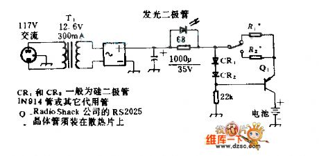
In this circuit, R1 is the 10Ω resistance, R2 is the 200Ω resistance. When the switch closes up, the charging current is 60mA (constant-current); when the switch closes down, the charging current is 3mA (constant-current). The total pressure drop of the silicon diode CR1 and CR2 are 1.2V, but Q1's launch pressure drop is 0.6V, so R1 or R2's net pressure drop is 0.6V. The 0.6V is divided by the required charge current, we get the resistance of R1 or R2. The LED indicates the charging circuit's working state.
(View)
View full Circuit Diagram | Comments | Reading(572)
transistor UMD6N and EMD6 internal circuits
Published:2011/5/16 20:42:00 Author:Christina | Keyword: transistor, internal circuit
Thetransistor UMD6N and EMD6 internal circuits:
(View)
View full Circuit Diagram | Comments | Reading(389)
The oxygen sensor detection circuit of Santana 20OOGLi
Published:2011/5/16 7:34:00 Author:Borg | Keyword: oxygen sensor, detection circuit, Santana


To detect if the oxygen sensor is normal, apart from testing circuits and sensors with digital multimeter, V.AGl551 diagnosis instrument can do some further tests, too.To do the detection, the temperature of engine coolant should be above 80℃, after the detection, idling speed should be normal, ventilation without leakage, the power supply of heating components inside oxygen sensor normal, resistance all right.(1)connect the VAG1551 diagnosis instrument, choose the functions codes of 01, enter the address of engine electric spray controller. When the screen shows fast data transportation , choose the assistance function of XX'.
(View)
View full Circuit Diagram | Comments | Reading(348)
TDA2030 amplifier circuit single-supply connection method circuit
Published:2011/5/16 20:52:00 Author:Christina | Keyword: amplifier circuit, single-supply, connection method

Integrated circuit TDA2030's single power amplifier connection method is as shown, the rated power is 14W. The power supply voltage is ±6~±18V. The output current is strong, and the harmonic distortion and the crossover distortion are small (±14V/4Ω,THD=0.5%).
(View)
View full Circuit Diagram | Comments | Reading(6601)
D/A converter DAC0832 circuit
Published:2011/5/16 9:26:00 Author:Christina | Keyword: D/A, converter


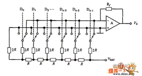
The DAC0832 uses the monolithic dc output type 8 digit/mode converter with the CMOS technology. As the figure 1 shows, this device is composed of the inverted T-type R-2R resistor network, the analog switch, the operational amplifier and the reference voltage VREF. The operational amplifier's output analog quantity V0 is:
Figure 1
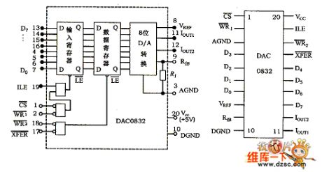
One 8-bit D/A converter has eight input ports (each input port is one of the eight binary number) and one analog output port. The input can have 28=256 different binary configurations, the output is one of the 256 voltages, this means the output voltage is not any value of the whole voltage range, it can only be 256 possible values. Figure 2 shows the DAC0832's logic diagram and pin arrangement.
Figure 2
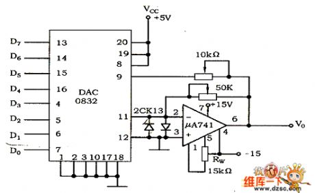
Figure 3
(View)
View full Circuit Diagram | Comments | Reading(4124)
Equivalent Circuit of Wireless Remote Transmitter
Published:2011/5/16 20:44:00 Author:Michel | Keyword: Wireless Remote Transmitter, Equivalent Circuit
View full Circuit Diagram | Comments | Reading(712)
3V Miniature Wireless Microphone Ciruit
Published:2011/5/16 9:17:00 Author:Michel | Keyword: 3V, Miniature Wireless Microphone, Ciruit
View full Circuit Diagram | Comments | Reading(1015)
MT8880 Interface Circuit
Published:2011/5/16 9:12:00 Author:Michel | Keyword: Interface Circuit
View full Circuit Diagram | Comments | Reading(1777)
Basic Part Number Regulating Circuit
Published:2011/5/16 9:01:00 Author:Michel | Keyword: Basic Part Number, Regulating Circuit
View full Circuit Diagram | Comments | Reading(606)
PH Meter Circuit
Published:2011/5/16 9:04:00 Author:Michel | Keyword: PH Meter, Circuit
View full Circuit Diagram | Comments | Reading(1351)
Clamp Circuit
Published:2011/5/16 21:07:00 Author:Sharon | Keyword: Clamp

Clamp circuit is a circuit that clamps the output potential unchanged at a value. Clamp circuit working principle: Let the diode as ideal component, when the input UA = UB = 3V, the diode V1 and V2 are forward-bias conducted, and the output is clamped at UA and UB, ie, UF = 3V; when UA = 0V, UB = 3V, V1 is conducted, and the output is clamped at UF = UA = 0V, V2 is anti-bias cut-off. (View)
View full Circuit Diagram | Comments | Reading(507)
Outdoor light automatic control principle circuit
Published:2011/5/16 22:35:00 Author:Christina | Keyword: Outdoor light, automatic control, principle

When you close the power switch S, the 220V city electricity gets to the transformer T1's primary stage through the fuse FU4, and the subprime output voltage (16V) is rectified by the rectifier bridge UR, then it gets through the regulator integrated block IC1, capacitance C1, C2's filters supply the operating power to the control circuit. IC2 and IC3 are the NE555 manifolds, the light control circuit is composed of the IC2 and the external components, the timing circuit is composed of the IC3 and the external components. The light is strong during the day time, so the photoresistor RG's resistance is small, the IC pin-24 reset terminal has the low-level voltage, transistor VT1 closes and the relay K1 cuts off, it's normally open contact points K1-1 and K1-2 cut off too, all the bulbs are not bright.
Figure: Outdoor light automatic control principle circuit (View)
View full Circuit Diagram | Comments | Reading(594)
Ring Modulator Circuit
Published:2011/5/16 21:16:00 Author:Sharon | Keyword: Ring Modulator

Ring Modulator Circuit is shown in the figure. (View)
View full Circuit Diagram | Comments | Reading(2732)
| Pages:1867/2234 At 2018611862186318641865186618671868186918701871187218731874187518761877187818791880Under 20 |
Circuit Categories
power supply circuit
Amplifier Circuit
Basic Circuit
LED and Light Circuit
Sensor Circuit
Signal Processing
Electrical Equipment Circuit
Control Circuit
Remote Control Circuit
A/D-D/A Converter Circuit
Audio Circuit
Measuring and Test Circuit
Communication Circuit
Computer-Related Circuit
555 Circuit
Automotive Circuit
Repairing Circuit


