power supply circuit
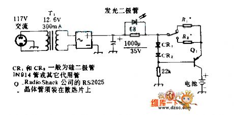
Cadmium nickel battery charging circuit
Published:2011/5/16 20:29:00 Author:Christina | Keyword: Cadmium, nickel, battery charging | From:SeekIC

In this circuit, R1 is the 10Ω resistance, R2 is the 200Ω resistance. When the switch closes up, the charging current is 60mA (constant-current); when the switch closes down, the charging current is 3mA (constant-current). The total pressure drop of the silicon diode CR1 and CR2 are 1.2V, but Q1's launch pressure drop is 0.6V, so R1 or R2's net pressure drop is 0.6V. The 0.6V is divided by the required charge current, we get the resistance of R1 or R2. The LED indicates the charging circuit's working state.
Reprinted Url Of This Article:
http://www.seekic.com/circuit_diagram/Power_Supply_Circuit/Cadmium_nickel_battery_charging_circuit.html
Print this Page | Comments | Reading(3)

Article Categories
power supply circuit
Amplifier Circuit
Basic Circuit
LED and Light Circuit
Sensor Circuit
Signal Processing
Electrical Equipment Circuit
Control Circuit
Remote Control Circuit
A/D-D/A Converter Circuit
Audio Circuit
Measuring and Test Circuit
Communication Circuit
Computer-Related Circuit
555 Circuit
Automotive Circuit
Repairing Circuit
Code: