Circuit Diagram
Index 1874
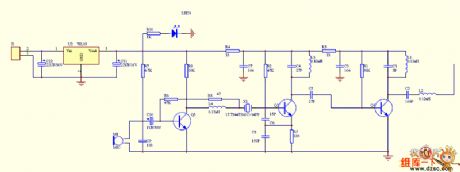
wireless hands-free phone circuit
Published:2011/5/16 3:17:00 Author:chopper | Keyword: wireless hands-free phone

wireless hands-free phone circuit is shown in following picture:
(View)
View full Circuit Diagram | Comments | Reading(624)
bridge amplifier circuit
Published:2011/5/16 3:12:00 Author:chopper | Keyword: bridge amplifier
View full Circuit Diagram | Comments | Reading(610)
exact clamper circuit
Published:2011/5/15 6:18:00 Author:chopper | Keyword: exact clamper
View full Circuit Diagram | Comments | Reading(987)
Adjustable car battery charger circuit
Published:2011/5/16 4:22:00 Author:Christina | Keyword: Adjustable, car battery charger

The Adjustable car battery charger circuit is as shown:
(View)
View full Circuit Diagram | Comments | Reading(11376)
Digital capacitance tester circuit
Published:2011/5/16 3:49:00 Author:Christina | Keyword: Digital, capacitance, tester

The Digital capacitance tester circuit is as shown. The tester is composed of the time base pulse generator, the monostable trigger, the addition counter, the decoder, the driver and the LED digital tube. And the time base pulse generator is composed of the IC1b (1/2 556) and R6, R7, R8, W1, W2, C2, it's output pulse signal can be used as the count pulse of the counting circuit (IC3). The monostable trigger is composed of the IC1a (1/2 556) and the R3 ~ R5, Cx (DUT capacitor).etc, the width of the output trigger pulse is td = 1.1 (R3 ~ R5) Cx, the greater the DUT capacitor is, the greater the timing width of the trigger pulse is, the counting of the corresponding counter IC3 are more. (View)
View full Circuit Diagram | Comments | Reading(1720)
3583 op-amp circuit
Published:2011/5/16 4:20:00 Author:Christina | Keyword: op-amp

The 3583 op-amp circuit is as shown:
(View)
View full Circuit Diagram | Comments | Reading(481)
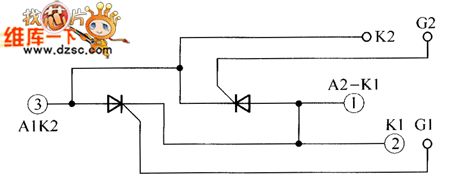
Transistor AK55GB40 and AK55GB80 internal circuits
Published:2011/5/16 4:13:00 Author:Christina | Keyword: Transistor, internal circuit

The Transistor AK55GB40 and AK55GB80 internal circuits are as shown:
(View)
View full Circuit Diagram | Comments | Reading(428)
Op-amp parallel circuit
Published:2011/5/16 4:19:00 Author:Christina | Keyword: Op-amp, parallel

The Op-amp parallel circuit is as shown:
(View)
View full Circuit Diagram | Comments | Reading(1380)
operational amplifier symbol and power connection circuit
Published:2011/5/16 3:38:00 Author:Christina | Keyword: operational amplifier, symbol, power connection

The operational amplifier symbol and power connection circuit is as shown:
(View)
View full Circuit Diagram | Comments | Reading(575)
4-channel keyboard control circuit
Published:2011/5/16 3:33:00 Author:Christina | Keyword: 4-channel, keyboard, control circuit
View full Circuit Diagram | Comments | Reading(663)
Low-pass filter circuit
Published:2011/5/16 3:29:00 Author:Christina | Keyword: Low-pass, filter

The Low-pass filter circuit is as shown:
(View)
View full Circuit Diagram | Comments | Reading(730)
Automatic weighing and measuring instrument circuit
Published:2011/5/16 3:28:00 Author:Christina | Keyword: Automatic, weighing, measuring, instrument circuit
View full Circuit Diagram | Comments | Reading(565)
Transmitter principle circuit
Published:2011/5/16 3:26:00 Author:Christina | Keyword: Transmitter, principle

The Transmitter principle circuit is as shown:
(View)
View full Circuit Diagram | Comments | Reading(645)
Simulation mechanical system circuit
Published:2011/5/16 3:17:00 Author:Christina | Keyword: Simulation, mechanical system

The Simulation mechanical system circuit is as shown:
(View)
View full Circuit Diagram | Comments | Reading(530)
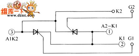
Transistor AK90GB80 and AK90HB120 internal circuits
Published:2011/5/16 3:21:00 Author:Christina | Keyword: Transistor, internal circuit


The Transistor AK90GB80, AK90HB120 internal circuits is as shown:
(View)
View full Circuit Diagram | Comments | Reading(488)
BA3570F-the integrated drive circuit of low-voltage headphone
Published:2011/5/14 8:00:00 Author:Borg | Keyword: drive circuit, low-voltage headphone


BA3570F is the integrated drive circuit of low-voltage headphone produced by Toyo Power Tool Corp.,Japan, which is widely used in walk-man.1.the typical application circuit of BA3570FThe typical application circuit of BA3570F is as shown in Figure 1, which characterizes with a Auto-matic Loudness Control System, i.e ALS.
2.the main parameters of BA3570FThe working power supply voltage of BA3570F ranges 2-7.2V, typical working voltages are 3V and 6V. When Vcc=3V,THD=1O% and RL=16Ω, the typical output power is Po=3OmWX2。3.pin functionsof BA3570FBA3570 is in flat 22-lead dual line package.
(View)
View full Circuit Diagram | Comments | Reading(1104)
DC motor-circuit detection circuit
Published:2011/5/16 3:11:00 Author:Christina | Keyword: DC, motor-circuit, detection

The DC motor-circuit detection circuit is as shown:
(View)
View full Circuit Diagram | Comments | Reading(538)
2N2222 wireless microphone circuit
Published:2011/5/16 2:57:00 Author:Christina | Keyword: wireless microphone
View full Circuit Diagram | Comments | Reading(4109)
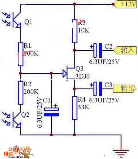
Light-control electronic potentiometer circuit
Published:2011/5/16 2:56:00 Author:Christina | Keyword: Light-control, electronic potentiometer

The Light-control electronic potentiometer circuit is as shown:
(View)
View full Circuit Diagram | Comments | Reading(498)
600MHz broadband amplifier circuit
Published:2011/5/16 2:51:00 Author:Christina | Keyword: 600MHz, broadband amplifier

The 600MHz broadband amplifier circuit is as shown:
(View)
View full Circuit Diagram | Comments | Reading(499)
| Pages:1874/2234 At 2018611862186318641865186618671868186918701871187218731874187518761877187818791880Under 20 |
Circuit Categories
power supply circuit
Amplifier Circuit
Basic Circuit
LED and Light Circuit
Sensor Circuit
Signal Processing
Electrical Equipment Circuit
Control Circuit
Remote Control Circuit
A/D-D/A Converter Circuit
Audio Circuit
Measuring and Test Circuit
Communication Circuit
Computer-Related Circuit
555 Circuit
Automotive Circuit
Repairing Circuit


