Circuit Diagram
Index 1435
ELECTRONIC_CW“BUG”KEYER
Published:2009/6/17 2:40:00 Author:May

This keyer uses skin conductivity to simulate the old-fashioned mechanical CW bug keyer. When the “dit”paddle is touched the bias on the inverter, IC1-a is shunted to ground, and it produces a logic high, causing oscillator sections C&D to generate a low-frequency square wave keying Ql for a series of “dits.” When the “dah”paddle is touched, section b produces a logic high, driving keyer Q1 on. (View)
View full Circuit Diagram | Comments | Reading(2349)
PRECISION_LIGHT_SENSITIVE_RELAY_SWITCH
Published:2009/6/17 2:40:00 Author:May

A CDS cell in a bridge circuit with an op amp provides a simple means of operating a relay at a predetermined light level. Potentiometer R4 sets the sensitivity. (View)
View full Circuit Diagram | Comments | Reading(1019)
CODE_PRACTICE_OSCILLATOR_USES_OPTOISOLATOR
Published:2009/6/17 2:37:00 Author:May

A slotted-pair isolator (A) is effectively an enclosed-pair isolator with a slit that will allow an obstacle to interrupt the light path. That could be useful for building a code key (B). (View)
View full Circuit Diagram | Comments | Reading(799)
PHOTOELECTRIC_SENSOR
Published:2009/6/17 2:37:00 Author:May

The circuit can be used as a sensor that can trigger an alarm without direct contact being madeby the intruder In this circuit,a visible or invisible tight Source radiates on the sensor,keeping thedetection loop In what could essentially be called a normally closed condition
As long as the light source striking R5 remalns uninterrupted,the switch remalns closed But ifan intruder passes between the light Source and the sensor,the circuit goes from closed to open,andtriggers the alarm.
A light-dependent resistor(LDR), whose resistance varles inversely in with the amount of lighthitting its sensitive surface,is used A bright light aimed at R5 causes its internal resistance to dropas low as a few hundred ohms;In total darkness,the unit’s resistance can rlse to several megohmsThe light-dependent resistor(R5) is conrtected between the +V supply and the base of Q1.As longas R5 detects light,it supplies ample base current to cause Q1's collector to saturate to near groundlevel That also pulls the base of Q2(a 2N3906 genera-purpose pnp transistor) to near ground level,turning it on and clamping its collector to the+V rail. (View)
View full Circuit Diagram | Comments | Reading(2534)
FAST_LOGARITHM_GENERATOR
Published:2009/6/17 2:37:00 Author:May

In this circuit, EOUT=(constant)×logEIN. The circuit should be useable with op amps other than the ones illustrated. (View)
View full Circuit Diagram | Comments | Reading(608)
BINARY_CLOCK
Published:2009/6/17 2:35:00 Author:May

This circuit is an unusual clock in that the LEDs are bi-color red/green displays that indicate the Lime in binary coded decimal form.LEDs 21 through 24 read out secondsLEDs 5, 18, 19, and 20 read out 105 secondsLEDs 14 through 17 read out in minutesLEDs 4, 11, 12, and 13 read out in 105 minutes LEDs 7 through 10 read out the hoursLEDs 1, 2, 3, and 6 read out tens of hoursThe 60-Hz line is used as a timebase. (View)
View full Circuit Diagram | Comments | Reading(2651)
DARK_ACTIVATED_SWITCH
Published:2009/6/17 2:34:00 Author:May

In this circuit, lowering of the light level on the CDS cell turns on Q1 and Q2 which switches on the load which could be a relay, light, etc. (View)
View full Circuit Diagram | Comments | Reading(133)
PORCH_LIGHT_CONTROL
Published:2009/6/17 2:33:00 Author:May

This circuit can control the on/off cycle of a light via a CDS photocell, and turn it off after a pre-set period. The light can only be turned on when CDS cell is in darkness, and it stays on for a time determined by the 555 circuit. On time depends on RI and C1 and is about 80 seconds with the values shown. (View)
View full Circuit Diagram | Comments | Reading(1011)
FUNCTION_GENERATOR_2
Published:2009/6/17 2:32:00 Author:May

A quad op amp makes up the heart of this function generator. U1-a generates a square wave, and outputs this to J3. J1 and J2 are pulse outputs obtained by differentiating the square wave. Integrator U1-b generates a triangle-wave shaper to obtain a sine wave. Q1 is an output amplifier. (View)
View full Circuit Diagram | Comments | Reading(2312)
DARK_ACTIVATED_RELAY_WITH_HYSTERESIS
Published:2009/6/17 2:32:00 Author:May

The hysteresis of a 555lC can be used to advantage for sensing a drop in light. An LDR or CDS cell with about 2 to 8 k resistance at desired light level should be used. (View)
View full Circuit Diagram | Comments | Reading(1224)
OUTDOOR_LIGHT_CONTROLLER
Published:2009/6/17 2:31:00 Author:May

A neon bulb and a CdS photocell enclosed in a light-tight enclosure forrn an optocoupler. A diac/triac combination is used to provide the snap-switch effect. A second CdS photocell acts as the main sensor.
As darkness approaches, the resistance of R4 begins to increase. At a threshold level, the diac triggers the triac and causes the neon bulb to light. This reduces the resistance of R6, causing the diac to trigger the triac, which lights the neon bulb and provides power to the load.As moming light comes up, the process is reversed. The neon bulb goes out and the SCR turns off. (View)
View full Circuit Diagram | Comments | Reading(1458)
COMBINED_LIGHT__DARK_ACTIVATED_SWITCH
Published:2009/6/17 2:30:00 Author:May

Two op arnps used in a bridge circuit configuration detect high and low light levels. Potentiometer R2 sets the dark level and R1 controls the light level. R3 is set so that about 1/2 the supply voltage appears across R4 at the desired light level. R1 and R2 set the trip point of the optoisolator IC2 at darker or lighter ambient levels, as required. (View)
View full Circuit Diagram | Comments | Reading(1001)
PRECISION_DARK_ACTIVATED_SWITCH_WITH_HYSTERESIS
Published:2009/6/17 2:29:00 Author:May

A CdS cellis one leg of a bridge circuit Potentiometer R6 In another leg sets the trip point Potentiometer R5 provides hysteresis adjustment to prevent “chattering” or hunting of the relay Thelight level has to increase noticeably before the 2N3904 turns off and the circuit deactivates. (View)
View full Circuit Diagram | Comments | Reading(592)
CARRIER_CURRENT_BABY_ALERT_RECEIVER
Published:2009/6/17 2:25:00 Author:May

The baby-alert receiver is comprised of three transistors: Q2, which is configured as a high-gain linear amplifier; Q3, which serves as both an amplifier and detector; and Q4, which is essentially used as a switch; and a few additional components. It sounds an alarm BZ1 on receipt of a 125-kHz signal from an alarm transmitter via the 120-V power lines. (View)
View full Circuit Diagram | Comments | Reading(565)
CARRIER_CURRENT_BABY_ALERT_TRANSMITTER
Published:2009/6/17 2:24:00 Author:May

The baby-alert transmitter is built around an LM334 quad op amp(U1), two LMC555CM CMOS oscillator/timers(U2 and U3), and a few support components. The transmitter sends a signal on receipt of a sound at MIC1. It has a frequency of around 125 kHz and can be used to trigger an alarm receiver. (View)
View full Circuit Diagram | Comments | Reading(2906)
SIMPLE_LIGHT_ACTIVATED_ALARM
Published:2009/6/17 2:23:00 Author:May

A cadmium-sulfide photocell conducts when a light beam strikes it. This triggers the SCR and activates the alarm device. (View)
View full Circuit Diagram | Comments | Reading(745)
LIGHT_DEPENDENT_SENSOR_FOR_MULTIPLE_INPUTS
Published:2009/6/17 2:22:00 Author:May

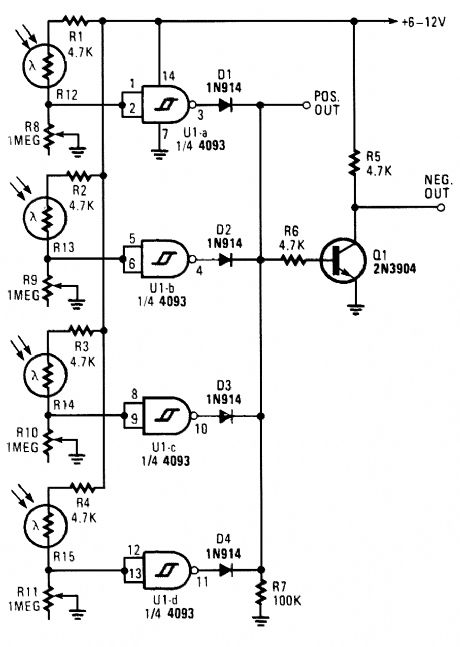
This light-dependent sensor uses LDRs to detect the presence or absence of light. As long as the light source striking the LDRs remains constant, the alarm does not sound. But when the light is interrupted, the alarm is triggered. (View)
View full Circuit Diagram | Comments | Reading(1052)
HALOGEN_LAMP_PROTECTOR
Published:2009/6/17 2:17:00 Author:May

This circuit produces a soft turn-on for halogen lamp filaments upon powerlng up,MOSFETRI used is a BUZ10, which has 0.2Ω RDS on.R1,R2,and C1 set the turn-on rate and D1 discharges C1 at turn-off. (View)
View full Circuit Diagram | Comments | Reading(953)
SENSITIVE_TRIAC_CONTROLLER
Published:2009/6/17 2:17:00 Author:May

The single transistor connected between the capacitor and the common side of the ac line allows a Iogic-level signal to control this triac power circuit. Resistor R2 prevents false triggering of the triac by the trickle current through the diac. (View)
View full Circuit Diagram | Comments | Reading(2592)
NEON_LAMP_DRIVER_FOR_9_V_SUPPLIES
Published:2009/6/17 2:13:00 Author:May

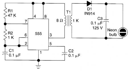
This circuit is for driving a neon lamp from a 9-V supply. The 555 generates an ac signal (stepped up by T1), and lights the neon bulb. T1 is any small audio output transformer. (View)
View full Circuit Diagram | Comments | Reading(3794)
| Pages:1435/2234 At 2014211422142314241425142614271428142914301431143214331434143514361437143814391440Under 20 |
Circuit Categories
power supply circuit
Amplifier Circuit
Basic Circuit
LED and Light Circuit
Sensor Circuit
Signal Processing
Electrical Equipment Circuit
Control Circuit
Remote Control Circuit
A/D-D/A Converter Circuit
Audio Circuit
Measuring and Test Circuit
Communication Circuit
Computer-Related Circuit
555 Circuit
Automotive Circuit
Repairing Circuit