
power supply circuit
Index 276
The second circuit of optical control integrated regulated power supply
Published:2011/3/30 22:09:00 Author:Nicole | Keyword: optical control, regulated power supply
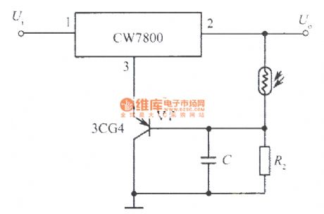
View full Circuit Diagram | Comments | Reading(427)
One of optical control integrated regulated power supply circuit
Published:2011/3/30 22:05:00 Author:Nicole | Keyword: optical control, regulated power supply
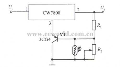
View full Circuit Diagram | Comments | Reading(458)
Simple regulator circuit
Published:2011/3/31 0:58:00 Author:Nicole | Keyword: regulator
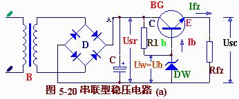
View full Circuit Diagram | Comments | Reading(452)
5V、5A regulated power supply composed of LM340T integrated regulator
Published:2011/4/6 0:38:00 Author:Nicole | Keyword: regulated power supply, integrated regulator
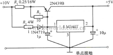
View full Circuit Diagram | Comments | Reading(655)
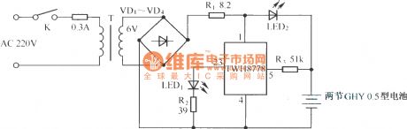
Memory doorbell circuit
Published:2011/4/5 23:53:00 Author:Nicole | Keyword: memoory, doorbell

Pressed doorbell switch K1, the doorbell phonation, lighted up LED D3; if there are nobody to open the door, guests leave, D3 still on, this means there were guests came.
Flip-flop is composed of T1, T2; D1, C1 form half wave rectification filter circuit, to support work voltage. (View)
View full Circuit Diagram | Comments | Reading(1117)
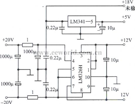
Multichannel regulated power supply composed of LM341-5, LM326H
Published:2011/4/6 0:34:00 Author:Nicole | Keyword: regulated power supply
View full Circuit Diagram | Comments | Reading(779)
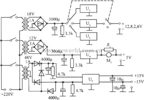
Multichannel regulated power supply composed of LM340 series
Published:2011/4/6 0:35:00 Author:Nicole | Keyword: regulated power supply
View full Circuit Diagram | Comments | Reading(753)
Simple mixed voltage regulator circuit
Published:2011/3/31 1:01:00 Author:Nicole | Keyword: voltage regulator
View full Circuit Diagram | Comments | Reading(536)
Simple Ni-Cd battery automatic pulse charger circuit(1)
Published:2011/3/31 1:09:00 Author:Nicole | Keyword: Ni-Cd battery, automatic pulse charger
View full Circuit Diagram | Comments | Reading(1877)
Simple Ni-Cd battery automatic pulse charger circuit(2)
Published:2011/3/31 1:10:00 Author:Nicole | Keyword: Ni-Cd battery, automatic pulse charger
View full Circuit Diagram | Comments | Reading(1257)
AC/DC 3 digits voltmeter circuit
Published:2011/4/5 22:51:00 Author:Nicole | Keyword: AC, DC, voltmeter

The input stage of this voltmeter circuit uses operational amplifier and diode feedback to form linearity peak value rectifier circuit. Through R2/R2 partial pressure isolation, it is sent to double multi-channel BCD output A/D converter CA3162E, it also can add 0~1V DC tested voltage to CA3162E differential input terminal between ⑩ and ⑾, If ⑩ is not used to connected ⑦, than it should need a resistance below 100kΩ to connect them.
The range of this voltmeter is 0~+0.99V, it only can display peak value about AC input voltage, if need to show AC effective value, it should decay transformation circuit appropriately. (View)
View full Circuit Diagram | Comments | Reading(3852)
Film loop speed control circuit
Published:2011/4/5 22:21:00 Author:Nicole | Keyword: film, loop speed
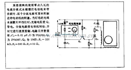
Some movie projectors use a few watts current separator permanent magnet induction motor to drive film, this divided circuit is used to control the rotational speed of motor. When the light is not blocked by film loop, photosensitive resistance makes Q1 conductive. Divided circuit makes motor flip, and also control its speed, circuit elements numerical take: C2=0.01μF, D is IN4004, Q1 is 2N4987, Q2 is 106B, R1=300kΩ, R2=100Ω, R3=10Ω. (View)
View full Circuit Diagram | Comments | Reading(540)
AC power supply dropping rapid detection circuit
Published:2011/4/5 21:08:00 Author:Nicole | Keyword: AC power supply, rapid detection
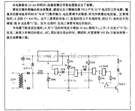
This circuit can detcet whether the AC power supply kicks up rapidly just in 10ms.
Source transformer secondary output through full-wave rectifier, filter and triple pin regulator 7812 produce 12V voltage power supply. Rectified ripple waveform is plastic outputed by NAND gate, sensitivity is adjusted by potentiometer, that is allowed drpoped voltage. Normally, in the point A, f=100Hz. Duing to the diode, the discharge time of C1 is shorter than its charge time, so Vc always could not reach the threshold, and the point B always in the 1 state . When K right dial, LED has corresponding instructions.
When the power supply is dropped into the set value, the time of A in the 1 state at least increase 10ms, in this period, Vc1 rises, B always in the 0 state, than LED has corresponding instructions too. RC2 is used to delay the instruction time. It can add 100Hz square wave to the first level inverter input terminal directly while debugging.
(View)
View full Circuit Diagram | Comments | Reading(874)
AC/DC clock circuit
Published:2011/4/5 21:55:00 Author:Nicole | Keyword: AC, DC, clock
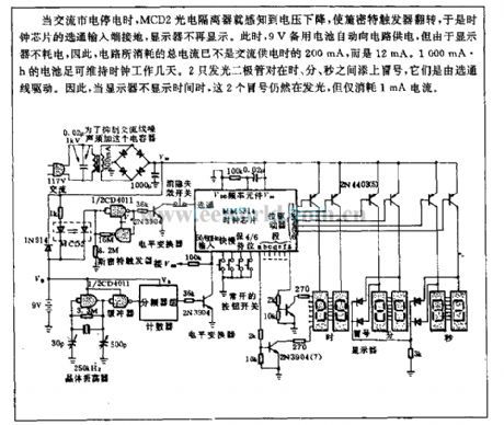
When AC municipal electric power is cut off, MCD2 photoelectric isolator perceives the voltage drop, made Schmitt trigger fliped, so the stobe input terminal of clock chip is grouding, the dispaly is not show again. Then the 9V reserve cell is charge to circuit automatically, but the display is no power consumption, so the total current of circuit consumption is not the 200mA AC power, but is 12mA. 1000mA*h battery can keep the clock work for a few days, 2 LEDs add colon betwwen hours, points and seconds, they are drived by gate line. so when the display don't show time, this two colons are still lightening , but only consume 1mA current.
(View)
View full Circuit Diagram | Comments | Reading(506)
Transformed single power supply into double power
Published:2011/4/1 22:15:00 Author:Nicole | Keyword: single power supply, double power


TDA2030 is a high efficiency operational amplifier. It uses its complement output stage, and divides the single power supply in two, then transformed into double power which is needed by some low power circuit.
The circuit diagram is shown above, R1, R2 have an equivalent resistance, and they form a divider to make the upper and lower voltage equal. The middle point of divider is connected to the in-phase input terminal of operational amplifier, operational amplifier is connected into voltage follower, to make the potential of O’ terminal and O terminal equal. O’ terminal is virtual ground point, it should be separated from input power supply ground.
If the double power is got from R1, R2 directly, then the power supply has high resistance, poor load capacity and little practical value. After using operational amplifier, the two groups of output power has low resistance and strong load capacity.
(View)
View full Circuit Diagram | Comments | Reading(2436)
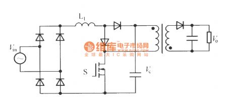
Based Boost single stage isolated type PFC converter
Published:2011/3/31 22:08:00 Author:Nicole | Keyword: PFC converter, isolated type
View full Circuit Diagram | Comments | Reading(564)
Based on DS2770 non-regulated power supply pulse charger
Published:2011/3/31 22:24:00 Author:Nicole | Keyword: non-regulated power supply, pulse charger
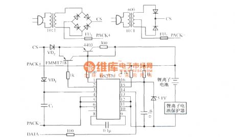
DS2770 is produced by Dallas Semiconductor, it is battery coulometer and lithium and nickel based chemistry battery charger control integrated chip, it can communicate with power management system through Dallasl-Wire interface, then to get the detection information, such as battery voltage and temperature, while read-write E2PROM, so it can be widely used in portable electronic devices. The figure of based on DS2770 non-regulated power supply pulse charger as shown.
(View)
View full Circuit Diagram | Comments | Reading(762)
Integrated regulated power supply circuit
Published:2011/4/1 1:03:00 Author:Nicole | Keyword: regulated power supply
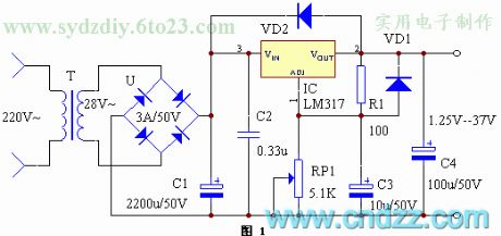
This is a integrated regulated power supply with continuously adjustable output, the output voltage is continuously adjustable between 1.25-37V, the maximum output current is up to 1.5A. The circuit is simple, and can be made by E-lovers, it is used for power supplying to all kinds of small electrical.
The circuit diagram is shown in figure1. LM317 output current is 1.5A, the output voltage can be continuously adjustabled between 1.25-37V, it is determined by two external resistors R1, RP1, the Voltage difference between output terminal and adjustment terminal is 1.25V, this voltage will produce a few milliamps current, to groud through R1, RP1, added the voltage from RP1 to adjustment terminal, the oputput voltage can be changed by changing RP1. A note which is, in order to obtain steady output voltage, the current flowing through R1 is less than 3.5mA. Without the radiator, the maximum power consumption of LM317 is 2W, with the 200×200×4mm3 radiator, then the maximum power consumption is 15W. VD1 is used to protect diode, prevent regulator output terminal from shorting and damaging IC, VD2 is used to prevent input shorting and damaging IC.
After weld and inspect to be flawless, the machine can be normal used, don't need to debug. When it is welding, capacitor C2 should close to the input terminal of IC, C3 should close to the output terminal, it is better to suppress ripple.
编 号
名 称
型 号
数 量
R1
电阻
100Ω
1
RP1
可调电阻
5.1K
1
C1
电解电容
2200u/50V
1
C2
涤纶电容
0.33u
1
C3
电解电容
10u/50V
1
C4
电解电容
100u/50V
1
VD1、VD2
整流二极管
IN4002
2
U
整流全桥
3A/50V
1
IC
可调三端稳压
LM317
1
T
电源变压器
28V
1
(View)
View full Circuit Diagram | Comments | Reading(558)
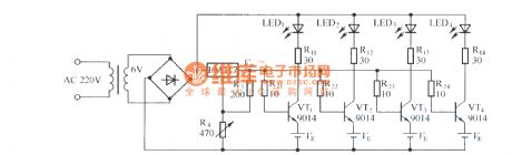
1.25W pulse occurring circuit used by LED
Published:2011/4/1 23:02:00 Author:Nicole | Keyword: pulse occurring circuit, LED
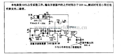
This circuit works with 50% duty cycle. The rise time of output square-wave pulse is lower than 200ns. It can use miniature lamp instead of LED to test.
(View)
View full Circuit Diagram | Comments | Reading(461)
Power modulation integrated circuit Y992
Published:2011/4/2 1:43:00 Author:Nicole | Keyword: power modulation
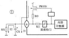
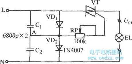
Y992 adopts one-terminal oscillation circuit, the internal circuit is as shown in the figure1. After the circuit is connected to power supply, PMOS tube charges to oscillation capacitor CX through resistance RO, the charge current is I1, the potential of capacitor CX is rising slowly. When it rises to the high threshold voltage of Smith, the output is from high level changed into low level, PMOS tube thuns off, capacitor CX vents its charge on resistance RO, the discharge current is I2. When the potential of capacitor CX is low to the low threshold voltage of Smith, the output changes into high level, then it starts to charge again, it forms a oscillation over and over again. One-terminal oscillator circuit onset simply and steadily. The oscillation frequency is decided by external connected RX and CX, the RX is in the range of 100kΩ~100MΩ, and the CX is in the range of 0.01~10μF, the oscillation frequency is between 10~0.1kHz.
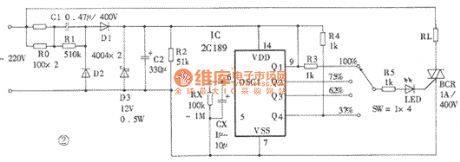
The power modulation circuit composed of Y992 is as shown in the figure2. Capacitors C1 and C2, diodes D1~D3 forms DC regulated power supply, charging to Y992. D3 selects 6 ~ 12V voltage regulator tube. The four gears switch can choose different power output. LED is lighted on when it has power, conversely, it is went out, so the LED can be used as power output indicator light. TRIAC is drive devices, 1A/400V thyristor can drive 200V load. The high power load can choose high power thyristor. According to needs to select oscillation resistance and capacitor, but the oscillation frequency can not higher than 50Hz.
(View)
View full Circuit Diagram | Comments | Reading(596)
| Pages:276/291 At 20261262263264265266267268269270271272273274275276277278279280Under 20 |
Circuit Categories
power supply circuit
Amplifier Circuit
Basic Circuit
LED and Light Circuit
Sensor Circuit
Signal Processing
Electrical Equipment Circuit
Control Circuit
Remote Control Circuit
A/D-D/A Converter Circuit
Audio Circuit
Measuring and Test Circuit
Communication Circuit
Computer-Related Circuit
555 Circuit
Automotive Circuit
Repairing Circuit