power supply circuit
Power modulation integrated circuit Y992
Published:2011/4/2 1:43:00 Author:Nicole | Keyword: power modulation | From:SeekIC


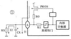
Y992 adopts one-terminal oscillation circuit, the internal circuit is as shown in the figure1. After the circuit is connected to power supply, PMOS tube charges to oscillation capacitor CX through resistance RO, the charge current is I1, the potential of capacitor CX is rising slowly. When it rises to the high threshold voltage of Smith, the output is from high level changed into low level, PMOS tube thuns off, capacitor CX vents its charge on resistance RO, the discharge current is I2. When the potential of capacitor CX is low to the low threshold voltage of Smith, the output changes into high level, then it starts to charge again, it forms a oscillation over and over again. One-terminal oscillator circuit onset simply and steadily. The oscillation frequency is decided by external connected RX and CX, the RX is in the range of 100kΩ~100MΩ, and the CX is in the range of 0.01~10μF, the oscillation frequency is between 10~0.1kHz.
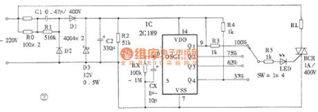
The power modulation circuit composed of Y992 is as shown in the figure2. Capacitors C1 and C2, diodes D1~D3 forms DC regulated power supply, charging to Y992. D3 selects 6 ~ 12V voltage regulator tube. The four gears switch can choose different power output. LED is lighted on when it has power, conversely, it is went out, so the LED can be used as power output indicator light. TRIAC is drive devices, 1A/400V thyristor can drive 200V load. The high power load can choose high power thyristor. According to needs to select oscillation resistance and capacitor, but the oscillation frequency can not higher than 50Hz.
Reprinted Url Of This Article:
http://www.seekic.com/circuit_diagram/Power_Supply_Circuit/Power_modulation_integrated_circuit_Y992.html
Print this Page | Comments | Reading(3)

Article Categories
power supply circuit
Amplifier Circuit
Basic Circuit
LED and Light Circuit
Sensor Circuit
Signal Processing
Electrical Equipment Circuit
Control Circuit
Remote Control Circuit
A/D-D/A Converter Circuit
Audio Circuit
Measuring and Test Circuit
Communication Circuit
Computer-Related Circuit
555 Circuit
Automotive Circuit
Repairing Circuit
Code: