
Index 15
Simple Micro Ampere Meter Circuit
Published:2013/12/1 20:25:00 Author:lynne | Keyword: Simple Micro Ampere Meter Circuit
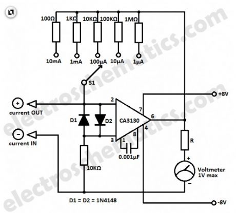
This simple micro ampere meter circuit can help in measuring small currents in five ranges: from 1 µA to 10 mA. The meter is working in this way: the current being measured Ix shifts the input voltage resulting to an output voltage with an inverted polarity.
The output voltage of the opamp CA3130 is proportional to the measured current Ix.By selecting the proper feedback resistors through S1, the output voltage by full meter deflection is 1 volt in all measuring ranges.
The value of the series resistor R must be selected for the particular meter being used. For example if a 1 mA meter is used, the total resistance (the sum of the resistor R and the coil resistance Ri of the meter) must be 1kΩ. If a 100 µA meter is used, the total resistance must be 100 kΩ. If needed, a potentiometer can be used for the R.
Micro ampere measurement circuit schematic
(View)
View full Circuit Diagram | Comments | Reading(1511)
Battery Charger Circuit, 12V
Published:2013/11/26 20:08:00 Author:lynne | Keyword: Battery Charger
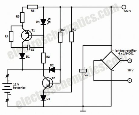
This battery charger circuit can be used to charge one or more batteries with the total nominal voltage of 12 V, meaning ten NiCd battery or six 2 V lead acid. The circuit is pretty small and can be built in a housing network adapter. The incorect usage is impossible: connecting the batteries with reverse polarity, shortcircuit of the output terminals or power loss have no impact on the charger or battery.
google_ad_client= ca-pub-9265205501290597 ;google_ad_slot= 6648404198 ;google_ad_width=336;google_ad_height=280;
We can use a transformer with 18 V on the secondary and then using a diode bridge to rectify the 18V ac voltage we get 22V dc on C1.
The completely discharged batteries are charged at the begining with a 6 mA current thru R2-D2 and R4-R6-D1. One the bat. have reached 0.3 – 0.5 V, the base-emitter voltage of T1 is high enough to bring the transistor in conduction.
Green LED D4 is used as an charging indicator and opens T1.There is a 60 mA current flowing thru R5-R6, this means that the charging of a 500 mAh NiCd battery will take 12 hours.
If the battery is connected with reversed polarity or there is a shortcircuit, the power transistor T1 remains blocked and the charging current can not exceed 6 – 12 mA. The current draw at maximum load is around 80 mA.
Battery charger circuit schematic