power supply circuit
OverVoltage Protection Circuit
Published:2013/10/22 21:52:00 Author:lynne | Keyword: OverVoltage Protection Circuit | From:SeekIC

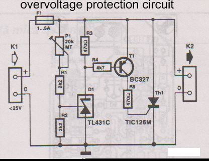
This overvoltage protection or crowbar protection circuit is used where we need protection against high voltage surge. The circuit has a few components, it is very easy to build and will protect your electric equipment againg overvoltages. The crowbar circuit must be mounted between power supply and the protected device.
The over voltage protection circuit is based on brute force: when the power supply voltage increases too much a thyristor shortcircuit the output. This mean that the overvoltage is quickly removed from equipment power terminals and F1 fuse will burn.
The voltage at which the crowbar protection starts is set between 5V and 25V with P1:
adjust P1 at maximum resistance value.
temporarily replace the fuse with a wire and connect the crowbar circuit at a variable power supply.
adjust the current limitation at 1 A si the output voltage at the desired value to activate crowbar protection.
slowly rotate P1 until activation of the thyristor (when the current limitator engages)
The overvoltage (crowbar) circuit is now set. Replace the wire bridge with a fuse (5A). In repaos state the circuit take 1 mA.
Over Voltage/Crowbar Protection Circuit Diagram
Reprinted Url Of This Article:
http://www.seekic.com/circuit_diagram/Power_Supply_Circuit/OverVoltage_Protection_Circuit.html
Print this Page | Comments | Reading(3)

Article Categories
power supply circuit
Amplifier Circuit
Basic Circuit
LED and Light Circuit
Sensor Circuit
Signal Processing
Electrical Equipment Circuit
Control Circuit
Remote Control Circuit
A/D-D/A Converter Circuit
Audio Circuit
Measuring and Test Circuit
Communication Circuit
Computer-Related Circuit
555 Circuit
Automotive Circuit
Repairing Circuit
Code: